Appendix
134 Installation and maintenance instructions aroTHERM plus 0020297937_01
Appendix
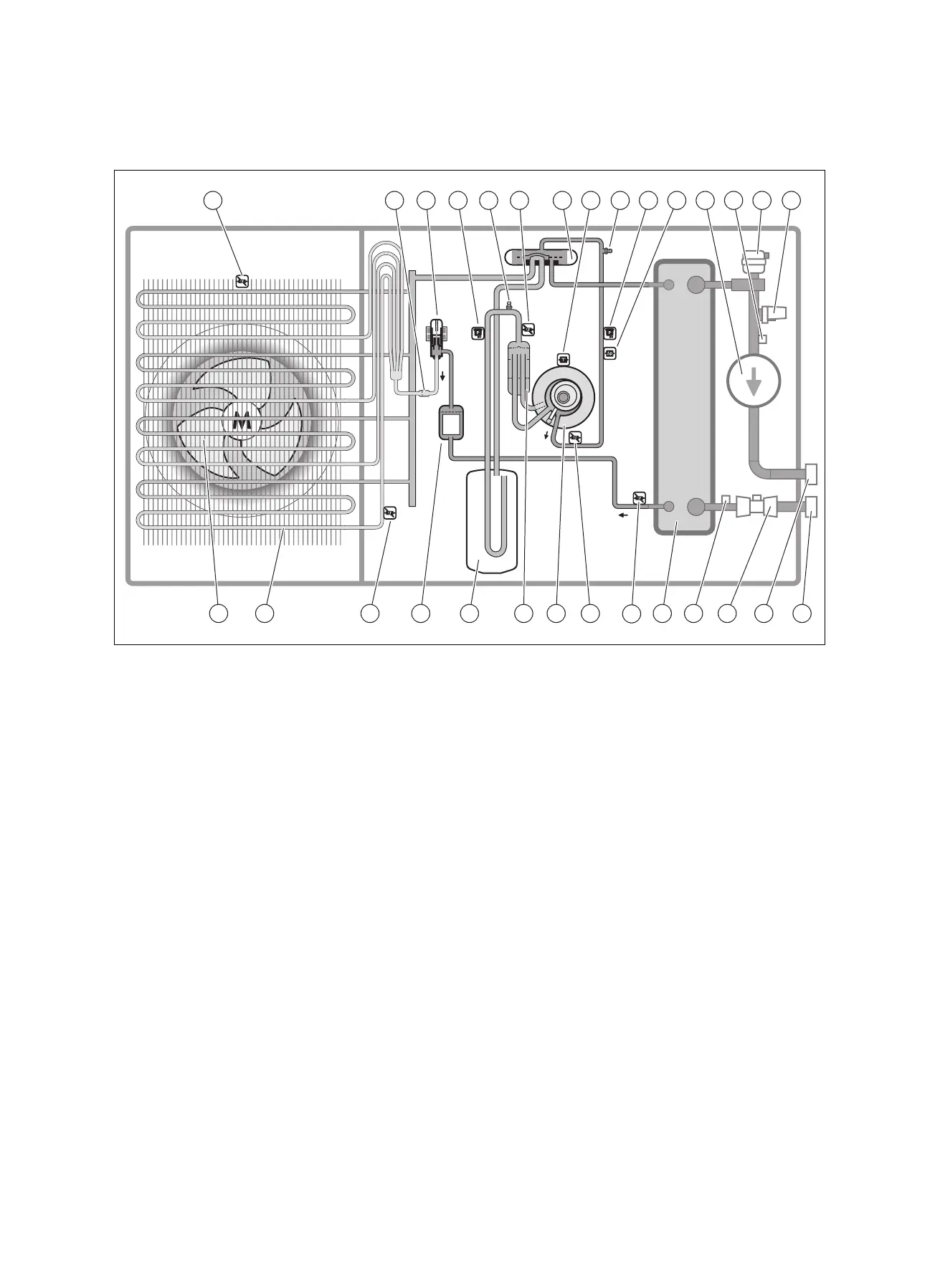
A Functional diagram
1 2 3 4 5 6 7 8 9 10 12 13 14 15
1617181920
21
2223242526272829
11
1 Temperature sensor, at the air inlet
2 Filter
3 Electronic expansion valve
4 Pressure sensor
5 Maintenance connection, in the low-pressure area
6 Temperature sensor, in front of the compressor
7 4-port diverter valve
8 Temperature sensor, on the compressor
9 Maintenance connection, in the high-pressure area
10 Pressure sensor
11 Pressure switch
12 Heating pump
13 Temperature sensor, on the heating flow
14 Automatic air vent, in the heating circuit
15 Pressure sensor, in the heating circuit
16 Connection, heating return
17 Connection, heating flow
18 Flow rate sensor
19 Temperature sensor, on the heating return
20 Condenser (heat exchanger)
21 Temperature sensor, behind the condenser
22 Temperature sensor, behind the compressor
23 Compressor
24 Refrigerant separator
25 Refrigerant buffer
26 Filter/dryer
27 Temperature sensor, at the evaporator
28 Evaporator (heat exchanger)
29 Fan
 Loading...