Appendix
0020297937_01 aroTHERM plus Installation and maintenance instructions 137
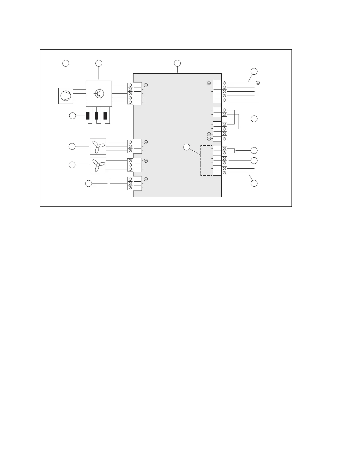
C.2 Wiring diagram, power supply, 3~/400V
3~/400V
1
2
3
4
5
5
4
3
2
1
S20
S21
BUS
eBUS
+
-
5
6
3
4
1
2
3
4
1
2
N
L3
L2
L1
L
N
1
2
L
N
L1
L2
L3
N
L1
L2
L3
N
3
2
1
L
N
3
2
1
L
N
X211
X210
X200
X201
X206
X214
X213
X212
3
2
1
L
N
2
3
11211
4
5
6
10
9
8
7
13
1 INSTALLER BOARD PCB
2 Power supply connection
3 Bridge, depending on the type of connection (energy
supply company lockout)
4 Input for the limit thermostat
5 Input S21, not used
6 eBUS line connection
7 Connection to the HMU PCB
8 Power supply for fan 2 (only for product VWL 125/6
and VWL 155/6)
9 Power supply for fan 1
10 Choking (only for product VWL 125/6 and
VWL 155/6)
11 Compressor
12 INVERTER assembly
13 Range for the safety extra-low voltage (SELV)