Installation 5
0020149486_04 auroFLOW plus Installation and maintenance instructions 11
5.11 The rules for laying the pipelines for the
solar circuit must be followed
▶ To prevent energy loss, all pipelines of the solar and cyl-
inder charging circuit must be fitted with heat insulation.
▶ To prevent heat losses, install the solar charger as near
to the collector field as possible; the minimum clearance
that must be observed is 1 m.
▶ Install the solar charger in a frost-proof room.
▶ To enable the collectors to drain, install the solar charger
lower than the collectors. The height difference between
the highest point of the system (top edge of the collector
field) and the lowest point of the system (bottom edge
of the solar charging system) must not exceed 6 m
(VPM 15 D) or 9 m (VPM 30 D) as, otherwise, the pump
output will be insufficient.
▶ Lay the connection lines between the collector field and
the solar charging system so that the downward gradient
is no less than 4% (4 cm/m) at any given point. This en-
sures that there is a sufficient solar fluid return.
▶ Do not lay more connection lines than allowed. Please
refer to the planning information.
5.12 Installing the basic module
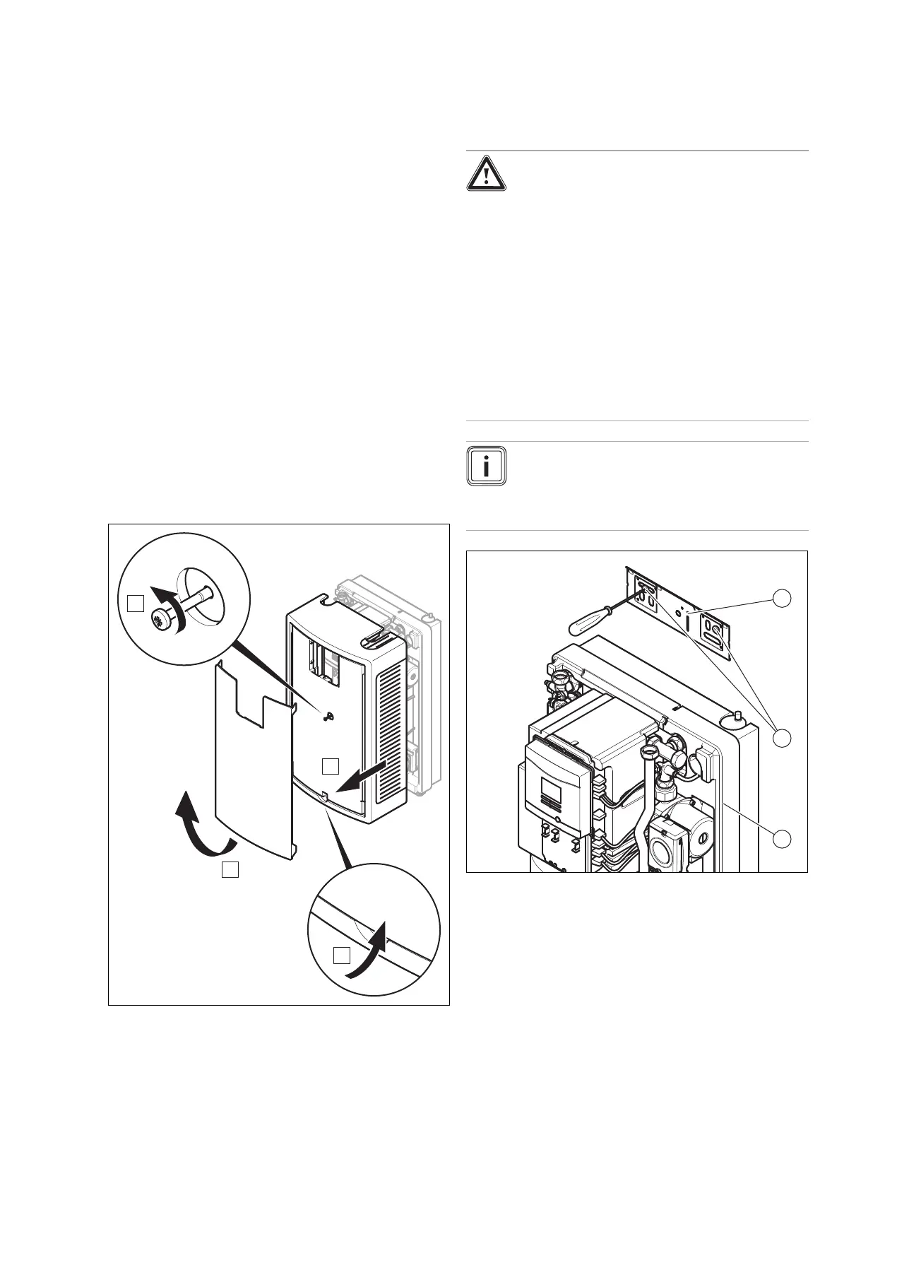
5.12.1 Removing the front casing
1. Take hold of the recessed handle at the bottom edge of
the white panel.
2. Pull the lower edge of the panel forwards and remove
the panel by pulling it upwards.
3. Undo the bolt.
4. Pull the front casing forwards and off.
5.12.2 Wall-mounting the basic module of the
solar charging system
Danger!
Risk of accidents as a result of insuffi-
cient load-bearing capacity of fixing ele-
ments.
If the fixing elements or wall do not have suf-
ficient load-bearing capacity, the product may
come loose and fall down. Solar fluid or heat-
ing water can be emitted from damaged lines.
▶ When installing the product, ensure that
the fixing elements and the wall have suffi-
cient load-bearing capacity.
▶ Check the quality of the wall.
▶ Make sure that the product is positioned
flush against the installation surface.
Note
If the expansion module is also being installed,
first mount the basic module, after it has been
suitably modified (see "Installing the expansion
module").
1. Use the installation template.
2. Mark the drill holes for the wall bracket on the wall.
3. Drill 2 holes with a diameter of 10 mm for the wall
bracket in the wall.
4. Fit the hanging bracket (1) to the wall using the rawl
plugs and screws provided (2).
5. Mount the product (3) from above onto the wall bracket
using the hanging bracket.
 Loading...