Installation 6
0020149486_04 auroFLOW plus Installation and maintenance instructions 13
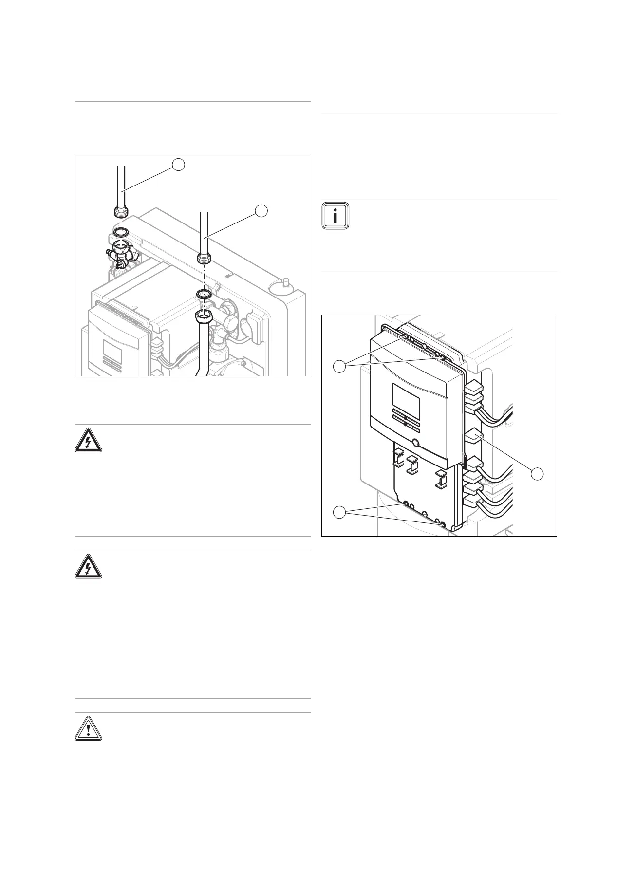
▶ Make sure that the collecting container is
visible.
▶ Install the discharge line (1) as shown.
6.1.3 Connecting the solar circuit
▶ Install the flow (1) and return (2) as shown.
6.2 Carrying out the electrical installation
Danger!
Risk of death from electric shock!
A continuous voltage is always present on
the mains connection terminals L and N.
▶ Disconnect the product from the power
mains by de-energising the product using
a partitionb with a contact opening of at
least 3 mm (e.g. fuses or power switches).
Danger!
Risk of death from electric shock as a res-
ult of an improper electrical connection!
An improper electrical connection may neg-
atively affect the operational safety of the
product and result in material damage or per-
sonal injury.
▶ The electrical installation must be carried
out by a suitably qualified competent per-
son who is responsible for complying with
the existing standards and directives.
Caution.
Risk of damage to the electrical lines as a
result of high temperatures.
The electrical lines may be damaged by the
high temperatures from the solar fluid that
flows through the copper pipes.
▶ Make sure that the electrical lines are
not positioned directly next to the pipes
through which the solar fluid flows.
▶ For the electrical installation of the product, observe the
technical connection requirements for connecting to the
low-voltage network of the power supply network oper-
ator.
6.2.1 Connecting the shift-load switching valve
Note
If a UV5 shift-load switching valve is included in
the hydraulic scheme, we recommend that you
use a 3-way valve from the Vaillant range of ac-
cessories and connect this using the connection
cable that is also available as an accessory.
Preliminary work
▶ Remove the front casing. (→ Page 11)
1. Route the supply lines of the shift-load switching valve
through the cable duct on the back of the product.
2. Undo the four bolts (1).
3. Open the controller casing.
4. Remove the dummy plugs (2).
 Loading...