2 Notes on the documentation
6 Installation and maintenance instructions auroFLOW plus 0020149486_04
2 Notes on the documentation
2.1 Observing other applicable documents
▶ You must observe all the operating and installation in-
structions included with the system components.
2.2 Storing documents
▶ Pass these instructions and all other applicable docu-
ments on to the system operator.
2.3 Validity of the instructions
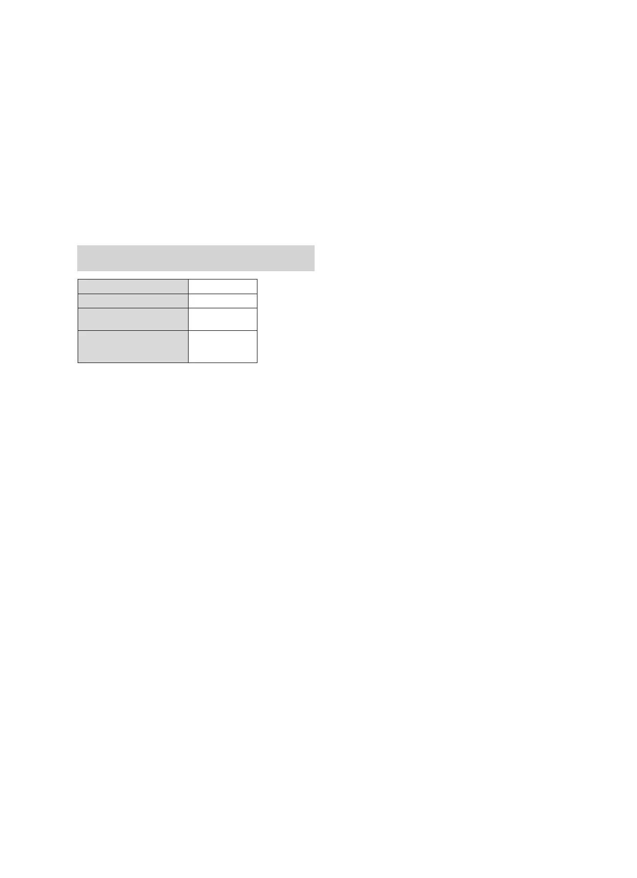
These instructions apply only to:
Product types and article numbers
Applicability: Belgium
OR Germany
VPM 15 D basic module
0020133195
Expansion module
0020133196
VPM 15 D basic module,
country-specific
0010013688
VPM 30 D basic module
with expansion module,
country-specific
0010013689
3 System
3.1 System characteristics
The solar system is described in the operating instructions.
3.2 Combination with system controller
The product can be combined with the auroMATIC VRS
620/3 system controller or the controller for the geoTHERM
heat pumps.
If you combine the product with the auroMATIC VRS 620/3
system controller, we recommend that you install a VPM ../2
W drinking water station.
3.3 Combination with cylinder
The solar charger can be combined with the following cylin-
ders:
– allSTOR
– auroSTOR
The cylinder charging circuit must be fitted on-site with a
safety device and expansion vessel. If an auroSTOR is in-
stalled, a safety device and expansion vessel are also re-
quired between the auroSTOR and solar charger.
Two diverter valves can be installed in the solar system.
1. The UV4, which is connected to the auroMATIC VRS
620/3:
First priority: allSTOR
Second priority: Swimming pool or other cylinder
2. The UV5, which is connected to the solar charger:
Switches between heating circuit and hot water circuit
for improved stratified charging
3.4 System conditions
The following conditions must be met by the solar system to
ensure correct operation:
– The solar charger must be installed below the collector
field
– The height difference between the bottom edge of
the solar charging system and the top edge of the
collector field must not exceed 6 m (VPM 15 D) or 9 m
(VPM 30 D).
– The solar lines must be installed with a downward gradi-
ent
– The maximum number of collectors must not be
exceeded
– The pipe diameters and lengths of the solar lines must be
observed
More precise information and hydraulic schemes can be
found in the planning information.
4 Product description
The product transmits thermal solar energy to a cylinder.
The following main components are integrated in the
product:
– Solar fluid storage tank
– Solar pump for the solar circuit
– Cylinder charging pump for the cylinder charging circuit
– Solar control for operating the pumps and recording of
the energy yield
– Heat exchanger between the solar and cylinder charging
circuit
 Loading...