Supplied By www.heating spares.co Tel. 0161 620 6677
23
PART 1 CONCENTRIC 60/100
INSTALLATION OF THE VARIABLE TERMINATION KIT
Variable termination kit
Accy. No.:
303 942 (black)
303 946 (white)
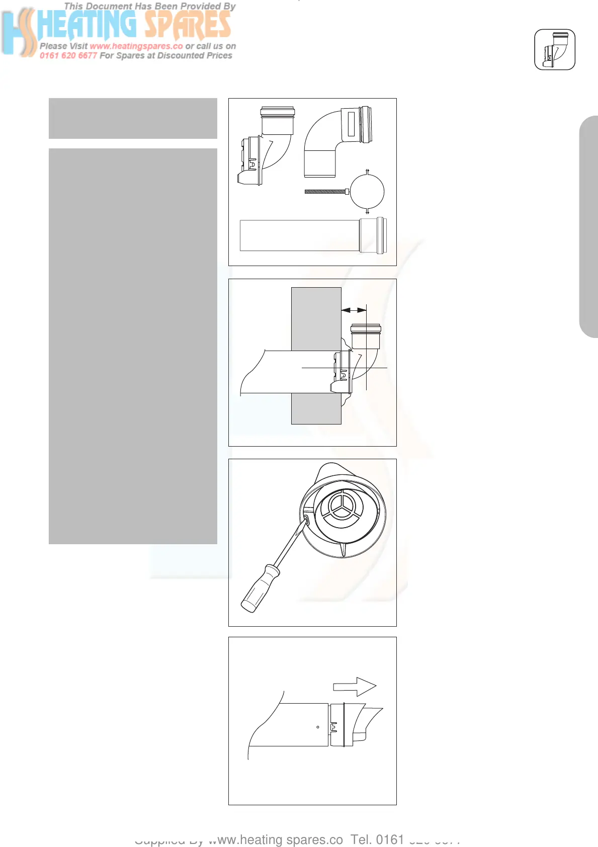
Contents of the kit:
• Variable terminal
• 2 x 1m pipe
• 3 x pipe support clips
• 87° bend with bird protection
grille
Important:
The flue outlet of the variable termi-
nation must face directly upwards.
Fig. 4.1: Variable termination kit
Assembly
Before installing the flue
pipe
• Use an 8 mm screwdriver to bend
the catches inwards (fig. 4.3).
• Pull the terminal with the flue duct
out of the air duct (fig. 4.4).
Fig. 4.4: Pulling out the variable terminal
Fig. 4.3: Releasing the catch
Fig. 4.2
Flue Terminal Clearances
Minimum flue terminal clearances
are defined in BS5440, and these
must apply unless the boiler manu-
facturer has received approval to
quote smaller clearances that are
not safety critical. Vaillant have re-
duced flue terminal clearances
approved and these are given in the
boiler installation instructions. These
are the minimum clearances that
must apply to all installations, except
when a Variable Termination Kit
(VTK) is fitted.
When a VTK is fitted to the horizon-
tal flue, the terminal clearances for
the air inlet are reduced. The termi-
nal clearances for the ‘new’ flue
outlet at the end of the VTK do not
change.
The minimum terminal clearances A,
B & C for the air inlet of the VTK are
reduced to 50 mm from an opening
such as a window, and 25mm from
an opening such as an airbrick. This
means that the terminal on the
horizontal flue becomes the air inlet
when a VTK is fitted, and hence can
be located less than 300mm from
an opening window or airbrick.
834449_09GB_082006.qxd 10.08.2006 12:20 Seite 23
 Loading...


