Supplied By www.heating spares.co Tel. 0161 620 6677
24
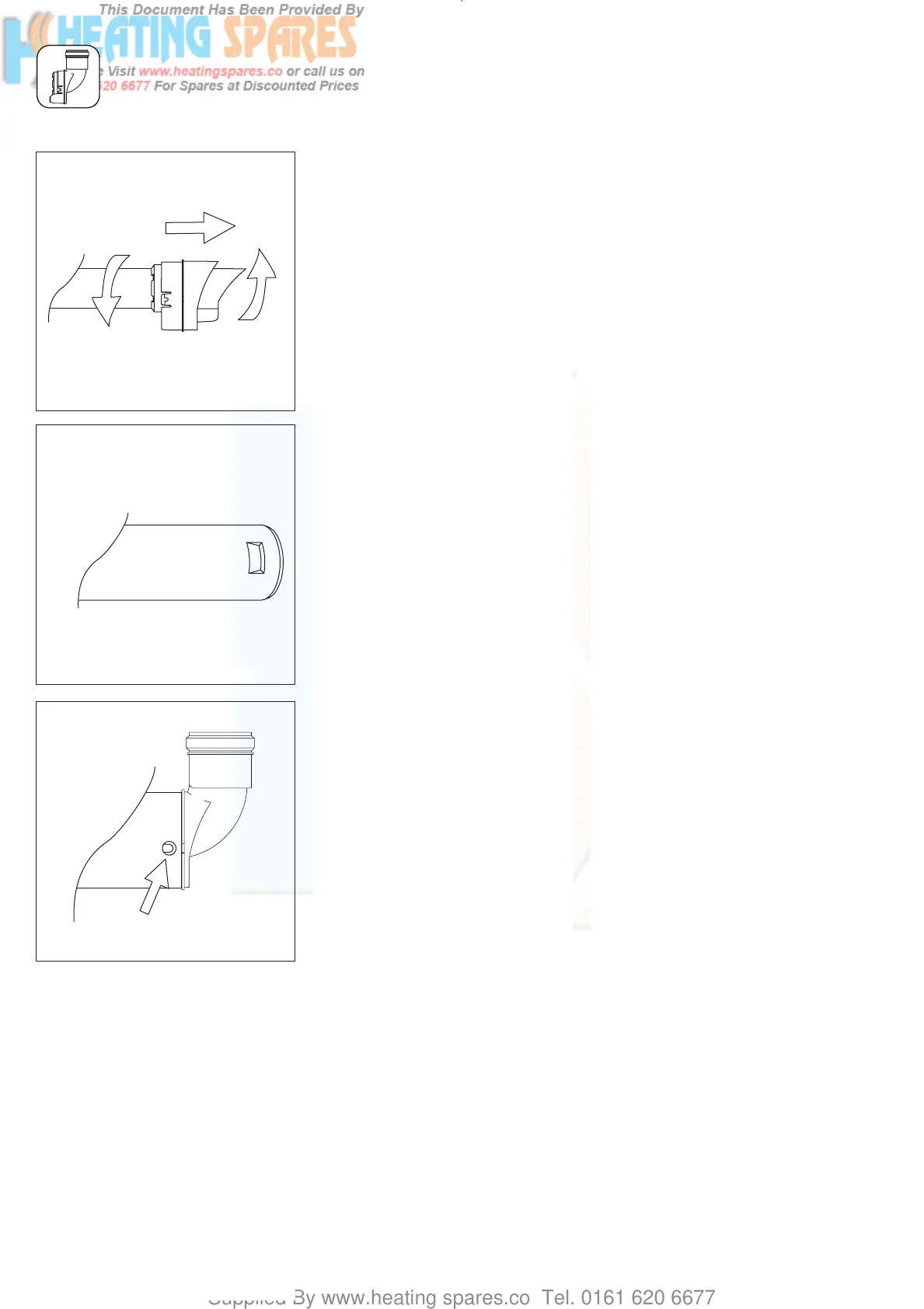
• Unlock the catch between the
terminal and the flue duct by
twisting them against each other
(fig. 4.5).
• Pull the terminal out of the flue
duct.
• Push the variable terminal onto the
flue duct.
☞ Please note: The catch on the top
of the variable terminal must lock
firmly into the notch in the flue
duct (fig. 4.6).
Caution!
Make sure the seal fits tightly.
• Push the flue duct and the variable
terminal back into the air duct
and lock the two catches
(fig. 4.7).
☞ Please note: The seam of the air
duct must be at the top.
• Fit the horizontal ait/flue duct as
described on pages 15 and 18.
Caution!
It cannot be fitted from inside.
• Fit the rest of the variable
termination kit as described on
page 25.
INSTALLATION OF THE VARIABLE TERMINATION KIT
Fig. 4.7: Locking the catch
Fig. 4.6: Flue pipe
Fig. 4.5: Unlocking the catch
Assembly
After installing the flue
duct
Danger!
Before starting work, shut down the
appliance and prevent it from being
switched on unintentionally.
• Remove the wall seal from the
terminal.
• Use an 8 mm screwdriver to bend
the catches inwards (fig. 4.3).
• Pull the terminal with the flue duct
out of the air duct (fig. 4.4).
Caution!
Do not twist the flue duct, because
this might detach the following flue
duct behind the terminal from the
spacer.
• Unlock the catch between the
terminal and the flue duct by
twisting them against each other
(fig. 4.5).
• Pull the terminal out of the flue
duct.
• Push the new variable terminal
onto the flue duct.
☞ Please note: The catch on the top
of the variable terminal must lock
firmly into the notch in the flue
duct (fig. 4.6).
☞ Please note: Make sure the seal
fits tightly.
• Push the flue duct with the
variable terminal back in the air
duct. Carefully push the flue duct
back into the sleeve of the duct or
bend behind it. Lock the two
catches (fig. 4.7).
• Fit the wall seal on the variable
terminal.
• Fit the rest of the VTK as
described on page 25.
Sie
834449_09GB_082006.qxd 10.08.2006 12:20 Seite 24
 Loading...


