0020308118_05 Installation and maintenance instructions 23
Validity: Product with integrated hot water generation
Condition: External expansion vessel installed and warm start active
▶ Install a non-return valve in the product outlet (heating
flow) or decommission the internal expansion vessel in
order to prevent the warm start function from being in-
creasingly activated due to backflow.
7.1.6 Softening water
For hard potable water with a degree of hardness of >15 °dH
(267 ppm CaCO₃; 2.67 mol/m³), it may make sense to soften
or stabilise the water or, in the case of domestic hot water,
this may be necessary in order to protect the potable water
installation.
Scale deposition increases as the water temperature in-
creases.
▶ Check whether the potable water may need to be
softened and, if required, soften the water.
▶ Use one of the technical options that complies with the
recognised rules of technology.
7.2 Installing the air/flue pipe
7.2.1 Room-sealed air/flue pipe
Note
This product range is only permitted for the C13,
C33, C43 and C53 unit types. Only room-sealed
installation is therefore permitted. Combustion air
supply from the installation room and adjacent
rooms is not permitted. The combustion air must
be supplied from outside of the building.
7.2.2 Regulation
Different flue outlet configurations can be carried out.
– Consult the installation manual for air/flue gas systems
for more information about the other possibilities and
associated accessories.
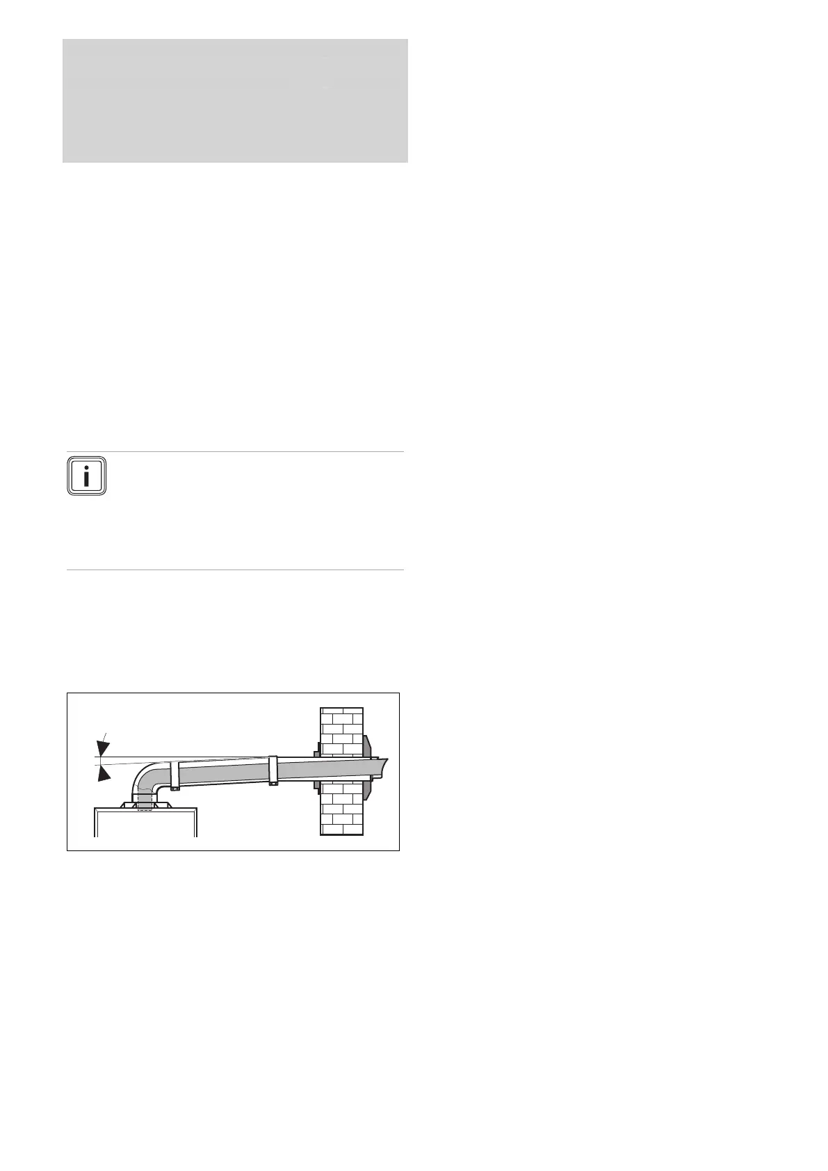
– Standard flue terminal kits have an in-built fall back to
the boiler to drain the condensate. These can be fitted
level between the appliance and the termination position.
All other extended flues must have a fall of at least 44
mm/m.
The maximum length of the flue outlet is defined according to
its type (for example C13).
– Whatever the kind of flue system chosen, observe the
minimum distances to position the flue terminals.
– To install the flue, refer to the separate flue instruction
supplied with your appliance.
– Explain these requirements to the user of the appliance.
In GB the minimum acceptable siting dimensions for the
terminal from obstructions, other terminals and ventilation
openings are shown in diagram overleaf.
In IE the minimum distances for flue terminal positioning
must be those detailed in I.S. 813 “Domestic Gas Installa-
tions”.
The terminal must be exposed to the external air, allowing
free passage of air across it at all times.
Being a condensing boiler some pluming may occur from
the flue outlet. This should be taken into consideration when
selecting the position for the terminal.

 Loading...


