32 Installation and maintenance instructions 0020308118_05
120 cm
2
4
0
cm
2
2
5
cm
1
0
2
1
2
1
60 cm
60 cm
225 cm
6
0
cm
60 cm
225 cm
6
0
c
m
2
1
2
1
1
2
0
1. Install the product outside of zones 0 and 1 (BS 7671)
(figure only used as a guide).
2. In all cases the installation must be in accordance with
the latest amendments to the latest edition of the IET
Wiring Regulations (BS 7671).
3. Check the IP rating of any control units to be used on
this appliance.
4. Connect the product with a fixed connection.
(→ Section 7.10.6)
5. For the power supply cable, use a flexible three-core
cable that complies with the relevant standards, which
is routed through the grommet into the product.
6. Connect the power supply cable to slot X1 on the PCB.
(→ Appendix L)
7. Observe the correct installation when routing the power
supply cable. (→ Section 13.7.15)
8. Ensure that the mains voltage is 230 V.
9. Install a suitable junction box.
10. Wire the power supply cable and the cable for the
house installation within the junction box.
11. Observe the flue-gas connection that is required on a
room-sealed air/flue system. (→ Section 7.2.5)
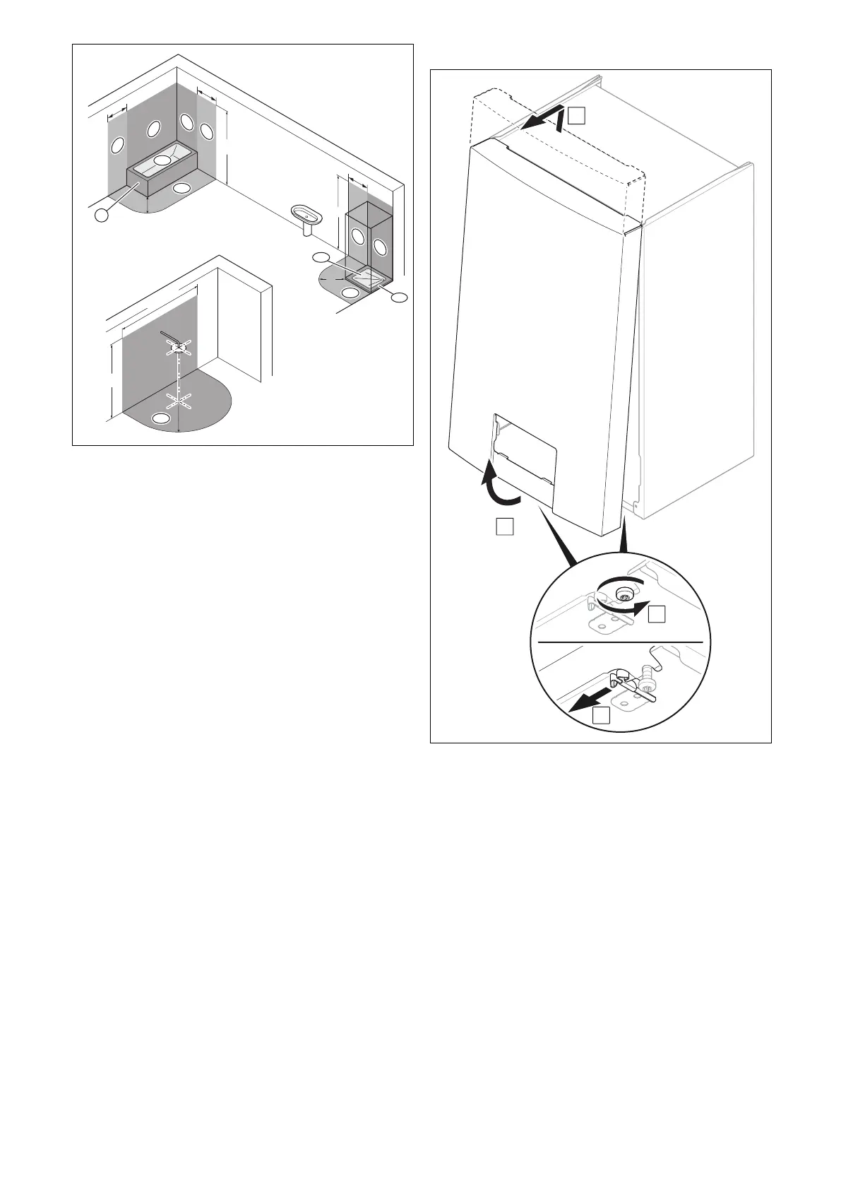
7.10.2 Removing the front casing
1. Loosen the two screws on the left and right on the un-
derside of the product, but do not unscrew them com-
pletely.
2. Remove the front casing as shown in the illustration.
 Loading...


