0020308118_05 Installation and maintenance instructions 65
xxxxxxxxxx
xxxxxx
xxxxxxxx
xxx
xxxxxx
xxxxxxxxxx
xxxxxx
xxxxxxxx
xxxxx
xxxxxx
xxxxxxxxxx
xxxxxx
xxxxxxxx
xxx
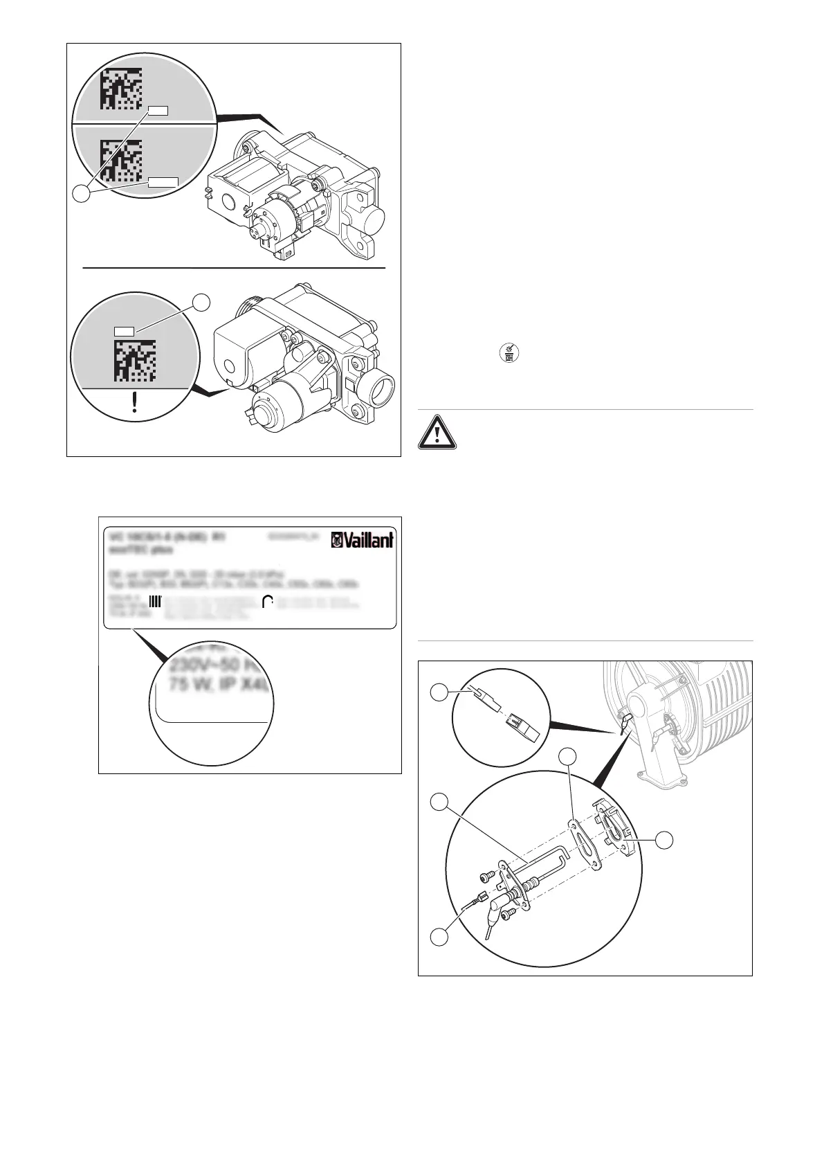
1. Read the offset (1) that is printed on the rear (type A)
or underside (type B) of the gas valve assembly and
note this down. Use a mirror, for example.
2.
Gas-Wandheizgerät mit Brennwerttechnik
Vaillant GmbH
Berghauser Str. 40 42859 Remscheid, Germany
DSN: XXX
as-Wandheizgerät mit Brennwerttechni
Read the DSN-Code (Device Specific Number) from
the data plate on the rear of the electronics box and
note this down.
3. Open the electronics box. (→ Section 7.10.3)
4. Replace the PCB and display according to the set-up
and installation instructions supplied; this is best done
one after the other. Doing so in this way means that
the old PCB can transfer the saved values to the new
display or, alternatively, the old display can transfer the
saved values to the new PCB.
5. Close the electronics box. (→ Section 7.10.4)
6. Replace the control electrode. (→ Section 13.7.14)
7. Install the front casing. (→ Section 7.11)
8. Establish the power supply.
9. ◁ After switching on, the product switches directly to
the menu to select the language.
10. Select the required language.
11. Set the read-off value DSN code (via D.093) for the
product type. (→ Section 8.3)
◁ The electronics are now set to the product type and
the parameters of all diagnostics codes are set to
factory settings.
◁ The installation assistant starts.
12. If the gas valve assembly offset that you read has five
digits, set diagnostics code D.052 using the first three
digits. (→ Section 8.3)
13. If the gas valve assembly offset that you read has three
digits, set diagnostics code D.052. (→ Section 8.3)
14. If the product is set with liquefied petroleum gas as the
gas type and the gas valve assembly offset that you
read has five digits, set diagnostics code D.182 using
the last two digits. (→ Section 8.3)
15. Check the installation-specific settings and adjust
these.
16. Start the test operation in chimney sweep mode by
pressing .
13.7.13 Replacing the ignition electrode
Danger!
Risk of death from hot flue gases!
Seals, screws and insulation on the control
electrode and combustion chamber must not
be damaged.
▶ Avoid damaging the burner insulating
mat on the back panel of the combustion
chamber cover.
▶ Replace the burner insulating mat as soon
as it shows signs of damage.
▶ Replace the seal and screws each time
you replace the control electrode.
1. Remove the earth cable (4).
2. Remove the plug (1) for the ignition electrode's cable.
3. Unscrew both screws.
4. Thread the ignition electrode (5) carefully out of the
burner flange (3). Ensure that you do not damage the
 Loading...


