0020308118_05 Installation and maintenance instructions 35
– Power supply: Single-phase, 230 V, 50 Hz
– Fuse protection: ≤ 3 A
4. Do not interrupt the mains supply with a time switch or
programmer.
5. For the power supply cable, use a flexible three-core
cable that complies with the relevant standards, which
is routed through the grommet into the product.
6. Connect the power supply cable to slot X1 on the PCB.
(→ Appendix L)
7. Observe the correct installation when routing the power
supply cable. (→ Section 13.7.15)
8. Ensure all electrical cables are in the correct cable
guides and away from hot appliance components.
9. Connect the product using a fixed connection and an
electrical partition with a contact gap of at least 3 mm
(e.g. fuses or power switches).
10. Isolation should preferably be by a double pole
switched fused spur box having a minimum contact
separation of 3 mm on each pole. The fused spur box
should be readily accessible and preferably adjacent to
the boiler. It should be identified as to its use.
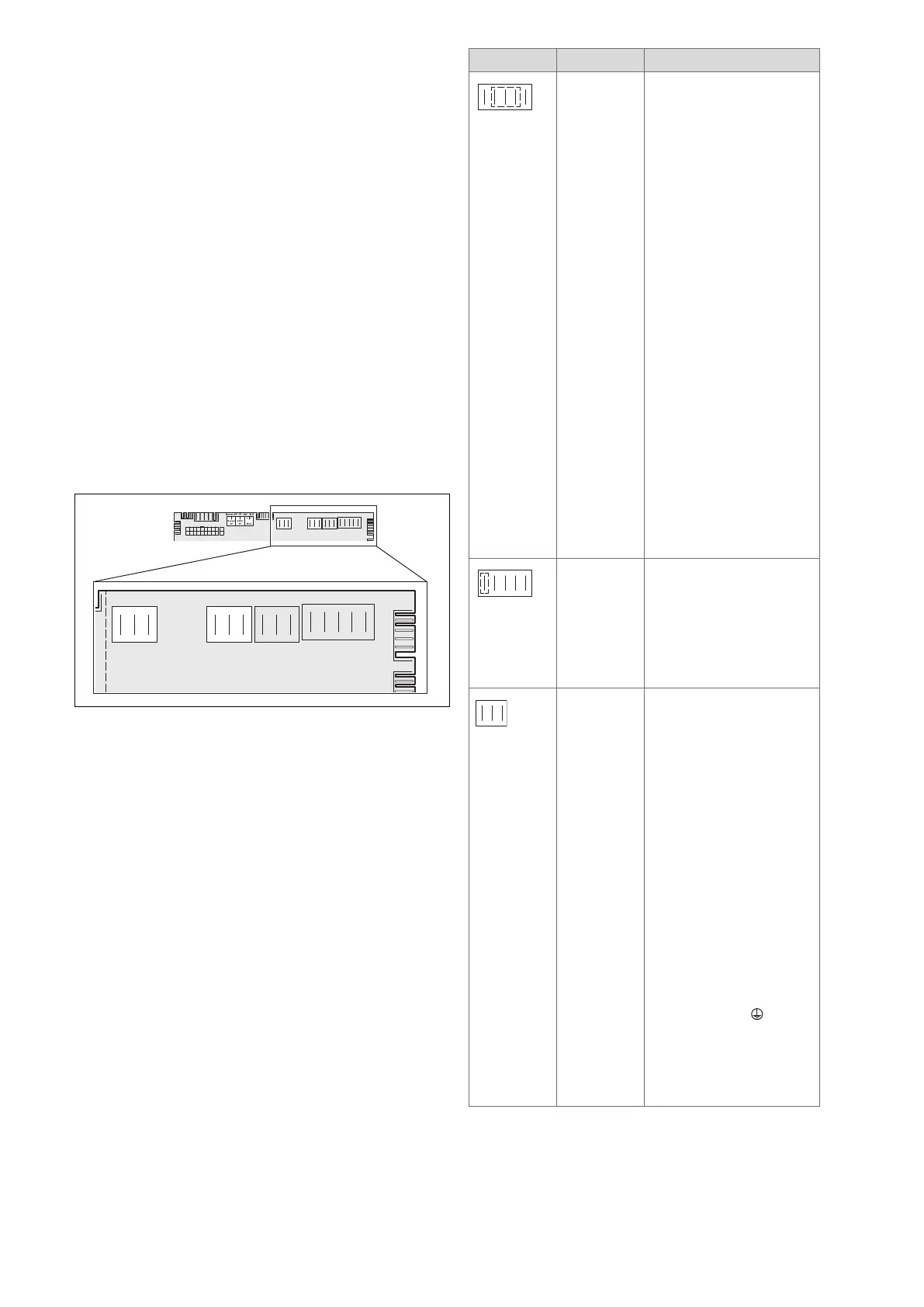
7.10.7 Connection options on the product
230 V connection area
X12b
X1
CH Pump
RT 230V Mains
X19
X41X36
X100
Opt 1
X16
Fan
X11
X24
X20
2a X12b
X1
CH Pump
RT 230V Mains
X19
Opt 1
X16
Fan
X11
– 230 V power supply
– Optional relay on the PCB
– 230 V room thermostat
Slot Item Function
X1 main power supply 230 V
input
Caution.
Risk of material damage due
to high connected voltage.
At mains voltages greater
than 253 V, electronic com-
ponents may be damaged.
► Ensure that the mains
voltage is 230 V
► Provide one common
power supply for the boiler
and for the corresponding
control:
– Power supply: Single-
phase, 230 V, 50 Hz
– Fuse protection: ≤ 3 A
► For the power supply
cable, use a flexible three-
core cable that complies
with the relevant standards,
which is routed through the
cable duct into the product.
► Connect the product us-
ing a fixed connection and
an electrical partition with
a contact gap of at least
3 mm (e.g. fuses or power
switches).
X1 230 V room thermostat
control
► Connect the switched live
supply of your 230 V RT to
the RT marked X1 position
(besides LNPE). Do NOT
connect the 230 V to any
other terminal, e.g. X100.
X16 Optional relay (230 V)
With diagnostic point D.026
you can use one function of
10 possible.
1. External pump/ 2. Circula-
tion pump/ 3. Solar cylinder
bypass valve/ 4. Anti-legion-
ella pump/ 5. eBUS remote
control/ 6. Solar pump/ 7.
External fault message/ 8.
External solenoid valve/ 9.
Extraction hood/ 10. Cylinder
charging pump
Note
An accessory is available in
order to use two additional
functions out of these ten
potential functions.
► Connect the connection
cable for the external button
to the terminals 1 0 and
6 (FB) on the X41 edge
connector, which is included
with the control.
► Plug the edge connector
into PCB slot X41.
 Loading...


