0020308118_05 Installation and maintenance instructions 67
Validity: VU 10CS/1-5 (N-GB) ecoTEC plus 610 OR VU 15CS/1-5
(N-GB) ecoTEC plus 615 OR VU 20CS/1-5 (N-GB) ecoTEC plus 620
OR VU 25CS/1-5 (N-GB) ecoTEC plus 625 OR VU 30CS/1-5 (N-GB)
ecoTEC plus 630 OR VUW 20/26CS/1-5 (N-GB) ecoTEC plus 826 OR
VUW 25/32CS/1-5 (N-GB) ecoTEC plus 832 OR VUW 30/36CS/1-5 (N-GB)
ecoTEC plus 836
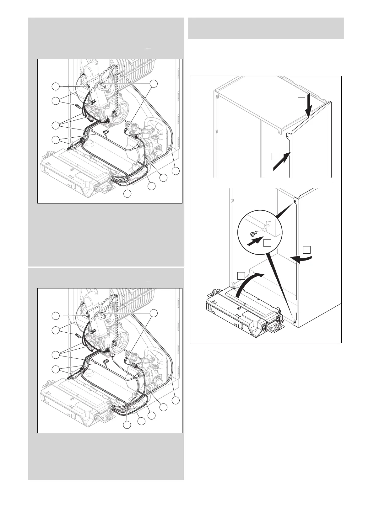
1 Hydraulics wiring
harness (impeller
water flow sensor,
water pressure sensor,
prioritising diverter
valve)
2 Wiring harness (fan,
gas valve assembly,
temperature sensors)
3 Ignition wiring harness
4 High-efficiency pump
cable
5 Socket cable
6 Power supply cable
Validity: VU 35CS/1-5 (N-GB) ecoTEC plus 635 OR VUW 30/40CS/1-5 (N-
GB) ecoTEC plus 840
1 Hydraulics wiring
harness (impeller
water flow sensor,
water pressure sensor,
prioritising diverter
valve)
2 Wiring harness (fan,
gas valve assembly,
temperature sensors)
3 Ignition wiring harness
4 High-efficiency pump
cable
5 Socket cable
6 Cable for 230 V fan
7 Power supply cable
1. Install the wiring harnesses as shown in the figure.
2. When plugging in the plug, observe the colour coding.
13.7.16 Completing repair work
1. If you have removed the side casing, install it as shown
in the figure.
2. Use two new screws to screw the side casing in tightly.
3. Open all service valves and the gas stopcock if this has
not yet been done.
4. Check the product for tightness. (→ Section 9.17)
5. Install the front casing. (→ Section 7.11)
6. If required, install the front panel below the display.
7. If required, install the modules below the product (→
Module installation instructions).
8. Establish the power supply if this has not yet been
done.
9. Switch the product back on if this has not yet been
done. (→ Section 9.4)

 Loading...


