0020308118_05 Installation and maintenance instructions 55
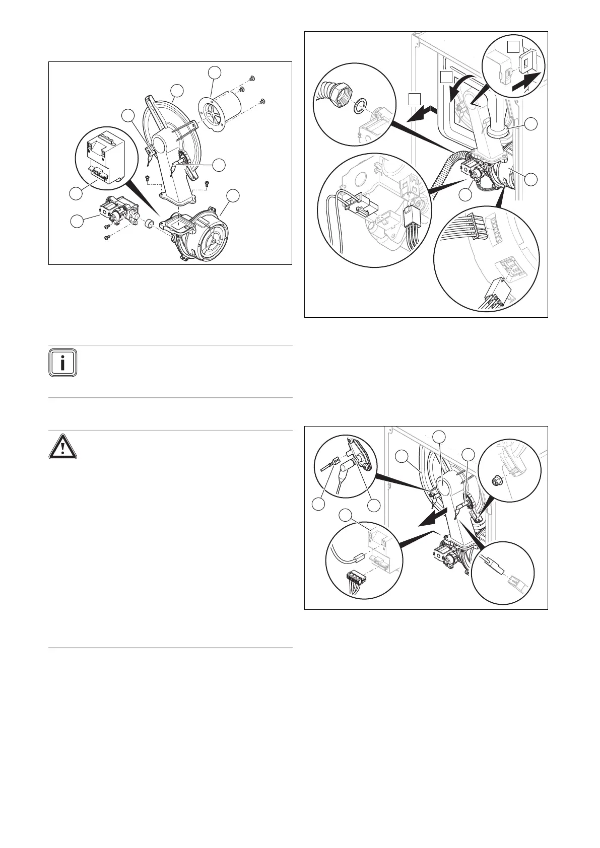
12.7 Removing/installing the compact thermal
module
1 Burner flange
2 Premix burner
3 Control electrode
4 Speed-regulated fan
5 Gas valve assembly
6 Ignition transformer
7 Ignition electrode
Note
Only touch the control electrode at the ceramic
section. Cleaning the control electrode is prohib-
ited.
12.7.1 Removing the compact thermal module
Danger!
Risk of death and risk of material damage
caused by hot flue gas.
The seal, insulating mat and self-locking nuts
on the burner flange must not be damaged.
Otherwise, hot flue gases may escape and
cause personal injury and material damage.
▶ Replace the seal each time you open the
burner flange.
▶ Replace the self-locking nuts on the
burner flange each time you open the
burner flange.
▶ If the insulating mat on the burner flange
or on the back wall of the heat exchanger
shows signs of damage, replace the insu-
lating mat.
1. Disconnect the product from the power supply.
2. Close the gas stopcock.
3. Remove the front casing. (→ Section 7.10.2)
4. Hinge the electronics box downwards.
5. Unscrew the air intake pipe (1) from the upper retainer
and remove the air intake pipe from the intake stub, as
shown in the figure.
6. Unscrew the union nut from the gas valve assembly
(3).
7. Remove the two plugs from the gas valve assembly .
8. Remove the plug or, if necessary, the two plugs from
the fan motor (2) by pushing in the latching lug.
9. Remove the earth cable (6) from the ignition electrode
(4), the two plugs from the ignition transformer (5) and
the plug for the control electrode's cable (3).
10. Remove the four nuts from the burner flange (2).
11. Remove the entire compact thermal module from the
heat exchanger (1).
12. Check the burner and burner insulating mat for dam-
age. (→ Section 12.8.3)
13. Check the heat exchanger for damage.
Result:
Heat exchanger damaged
▶ Replace the heat exchanger. (→ Section 13.7.8)
14. Check the heat exchanger for dirt.

 Loading...


