Installing the concentric connection to the air/flue gas system (LAS)
Installation manual for the flue pipe for ecoTEC plus 0020137851_02 19
7
7 Installing the concentric connection
to the air/flue gas system (LAS)
You require at least:
– The 87° elbow, dia. 110/160 mm
(article number 0020106380)
– An extension Ø110/160 mm (article number 0020106385)
a
Danger!
Risk of poisoning due to escaping flue
gas!
Standing condensate can damage the seals
of the flue gas pipe.
> Lay the horizontal flue pipe with a down-
ward gradient of 3° inwards. 3° corre-
sponds to a downward gradient of
approx. 50 mm per metre of pipe length.
a
Danger!
Risk of poisoning due to escaping flue
gas!
In the event of overpressure in the vertical
part of the flue gas pipe, flue gas may flow
into a unit that is not operating. The units
are not suitable for this mode of operation
and are not checked.
> Provide evidence of the functional relia-
bility of the vertical flue gas pipe in
accordance with EN 13384 using the
specifications for flue gas temperature
and flue gas mass rate from the installa-
tion instructions for the unit.
a
Danger!
Risk of injury due to damage to the
structural integrity.
The static function and fire-protective func-
tion of the shaft wall may be impaired and
may lead to a hazard to persons.
> Do not attach any fastenings using bolts,
rawl plugs, etc. directly to the shaft wall
of the air/flue gas system.
> Do not attach fastenings to primary wall-
ing or sideways to the wall.
> Observe the specifications provided by
the manufacturer of the air/flue gas
system.
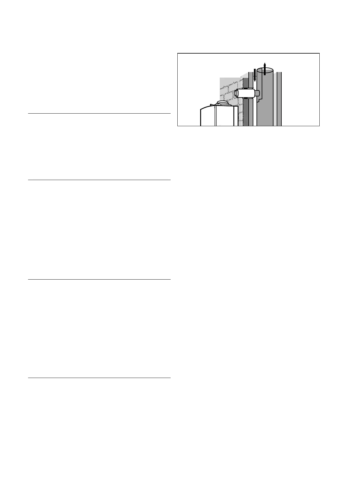
B
A
7.1 Shorten the flue pipe to the length required and insert the
air pipe
Key
A Air
B Flue gas
> On the air/flue gas system, establish a connection in
accordance with the dimensions in ¬section 3. These
dimensions allow for the lateral installation of the unit or
installation directly on the primary walling.
Ceramic air/flue gas systems are usually equipped with rub-
ber sealing sleeves and have a pipe stop on the air-side
connection.
> Separate the sleeve on the flue pipe so that you can
slide the flue pipe into the seal.
> Insert the air pipe into the sleeve of the air/flue gas sys-
tem.
> Insert the flue pipe into the flue seal of the air/flue gas
system. When fitting further elements, prevent the flue
pipe from sliding into the flue gas duct.
Metal air/flue gas systems feature cylindrical supports on
the flue-gas-side. In this case, insert the concentric flue
pipe with sleeve.
i
For air/flue gas system shafts that have no
sleeves, you must secure the air pipe using mor-
tar and seal the shaft.
> If applicable, install additional extensions and elbows
starting from the wall and working towards the unit.
> Attach one fastening clamp for each extension.
> Finally, insert the elbow of the flue gas pipe into the flue
gas connection of the unit.
> Connect all connecting points of the air pipes using a
safety screw as described in ¬ section 10.







 To Next Page