Installing the flue gas pipe on the external wall
20 Installation manual for the flue pipe for ecoTEC plus 0020137851_02
8
8 Installing the flue gas pipe on the
external wall
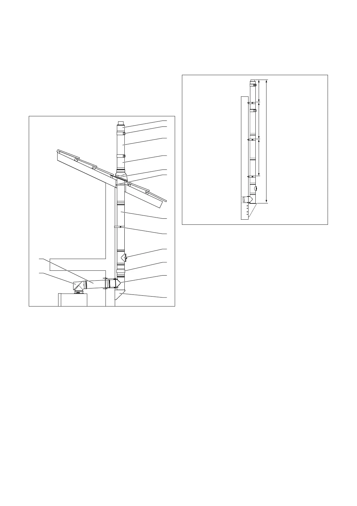
8.1 System diagram
1
3
4
5
6
7
8
9
10
11
12
2
13
14
8.1 System diagram of the flue gas pipe
Key
1 Opening piece
2 Clamp
3 Outer extension
4 Roof duct
5 Pitched roof tile
6 Fastening clamp
7 Extension
8 Pipe bracket
9 Inspection element (Not required in all countries)
10 Air intake piece
11 Support elbow
12 Support console
13 Internal extension
14 Inspection elbow (Not required in all countries)
8.2 Static dimensions
A
D
C
B
8.2 Static dimensions
Key
A: Max. 50 m (max. vertical height above the support console)
B: Max. 2 m (distance between the pipe brackets)
C: Max. 2 m ( distance between the two upper pipe brackets)
D: Max. 1.5 m (max. height above the last pipe bracket)
The dimension A specifies the maximum height of the flue
gas pipe above the support console.
If dimension A is exceeded, the load-bearing capacity of the
console is exceeded by the vertical weight.
To ensure that any wind forces can be safely absorbed,
dimension B must not be exceeded.
To ensure that any wind forces can be safely absorbed,
dimension C must not be exceeded.
Dimension D specifies the maximum height above the high-
est pipe bracket that cannot be exceeded due to wind
forces.







 To Next Page