8. GAS SUPPLY CONNECTION
A nut and olive are provided for an 8mm pipe inlet connection to the ‘T’ connector at
the bottom front of the appliance. The ‘T’ connector can be rotated to allow a
connection from any rear-concealed connection. The ‘T’ connector includes a valve
for isolating the gas supply and a pressure test point.
The supply pipe must be rigid material. Flexible pipe must not be used.
Concealed supply pipe connection.
If a concealed connection from inside the fireplace is required then, before the
appliance is fitted into the fireplace it will be necessary to extend the supply line so
that it will project through the hole in the back of the hotbox and run to the ‘T’
connector at the front. The pipe run from the supply line up to the rear opening in the
hotbox must be kept away from the area which will be taken by the hotbox when it is
installed. Note that the centre of the appliance inlet ‘T’ connector is 25mm above the
fireplace floor. The inlet ‘T’ connector should be fitted to the supply pipe at this stage.
9. PREPARING APPLIANCE FOR INSTALLATION
1. The fire is fitted with two transit support screws.
These are located on the sides of the hotbox and are
labelled. They prevent burner assembly movement
during transit. Remove the transit screws and discard.
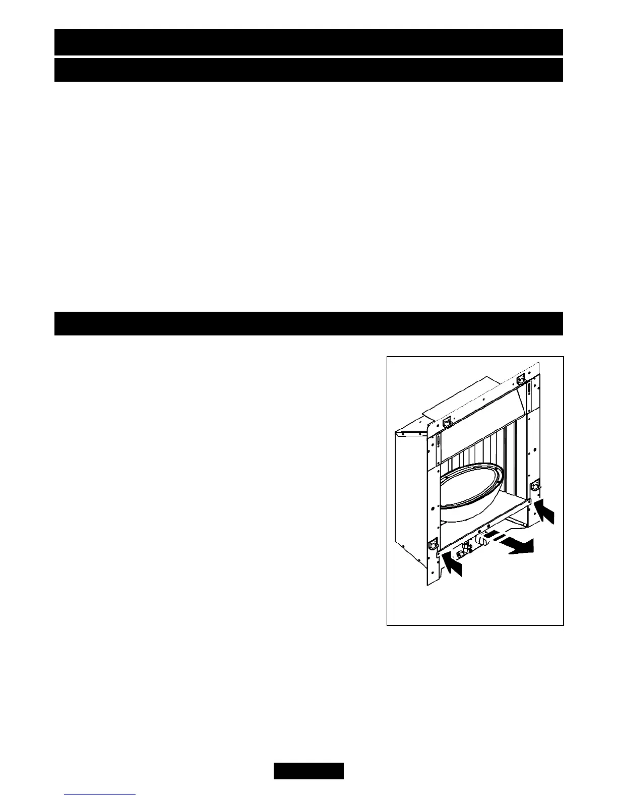
2. Remove the two screws to the side of the burner
assembly (See figure 10).
3. Detach the burner assembly from the hotbox by
holding the ‘bowl’ and gently sliding forward. The burner
assembly is heavy and if not supported sufficiently will
drop when clear of its support brackets. When sliding
the burner assembly be careful not to lift it as this may
scratch the top surface.
Page 20
© Baxi Heating U.K. Limited 2010.
Figure 10. Burner module
removal.
INSTALLER GUIDE