14. Feed the free length of the cables into the gap between the inner and outer back
panels so that they are available to allow easy removal and refitting of the appliance
during subsequent service calls. Do not cut off the free lengths of cable. On
precast flue installations feed the cables into the small holes at the base of the side
panels.
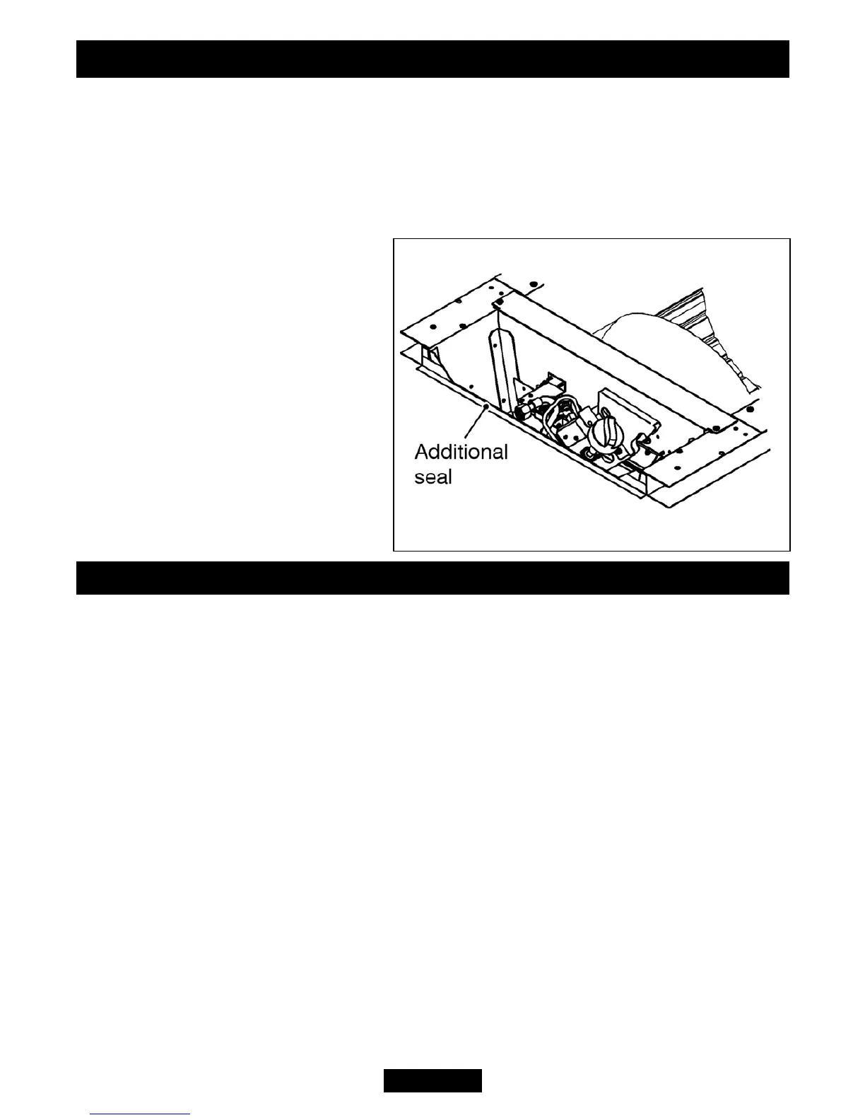
10.2 Sealing floor front - all installations.
The foam seal on the base should be
sufficient to seal the hotbox to the
floor. If the base of the fireplace
opening is uneven then a length of
sealing tape is supplied with the fire.
Using this, seal the bottom of the
hotbox to the fireplace (See figure
24).
Make sure that the whole length of
the front edge of the hotbox is fully
sealed.
11. BURNER & SUPPLY PIPE INSTALLATION
11.1 Fitting the burner.
1. Place the burner assembly into the hotbox and secure using the two screws
removed previously.
2. Supplied with the fire is an elliptical burner bezel. Place this within the edge of the
burner so that it covers the screws that secure the burner top surface. The gap in the
ellipse should be positioned so that the pilot flame passes through it.
11.2 Supply pipe installation.
A nut and olive is provided for an 8mm-pipe inlet connection directly to the gas
control. The isolating ‘T’ connector can be rotated to allow a connection from any
direction. The ‘T’ connector includes a valve for isolating the gas supply.
The supply pipe must be rigid material. Flexible pipe must not be used. Connect the
supply line to the appliance.
Turn on the gas supply and pressure check the installation pipework for gas
soundness. In the United Kingdom (GB) check in accordance with the current edition
of BS 6891. In the Republic of Ireland check in accordance with the current edition of
IS 813 “Domestic Gas Installations”.
Page 26
© Baxi Heating U.K. Limited 2010.
Figure 24. Floor sealing
INSTALLER GUIDE