25
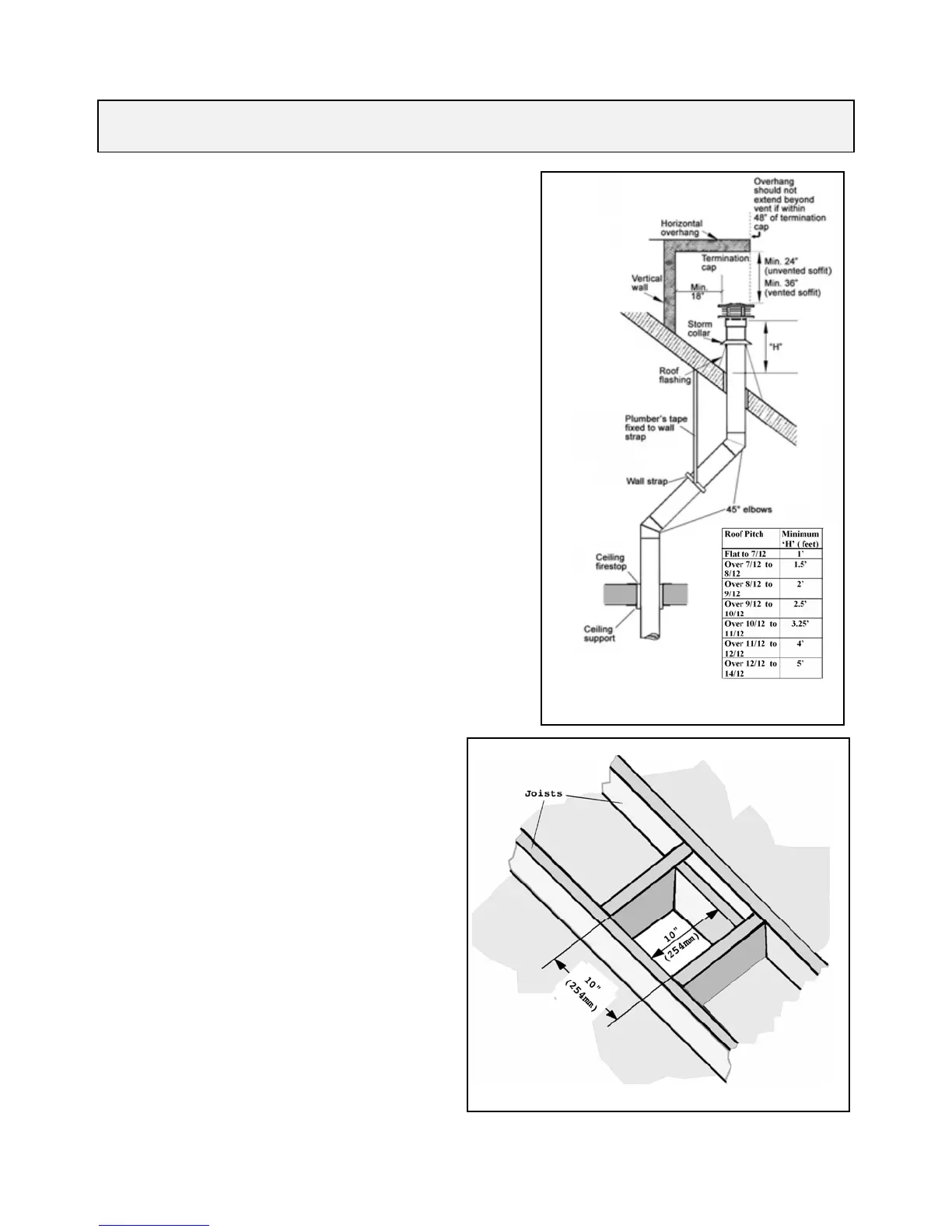
9.INSTALLATIONS WITH THROUGH THE ROOF VERTICAL
TERMINATION
• Check the roof pitch to determine which roof flashing will be needed
- see vent accessories section 2.4.
• The distance from the roof to the lowest terminal discharge opening
(“H” in figure 35) depends on the roof pitch and must be in
accordance with the manufacturer’s instructions supplied with the
termination unit.
Note: The venting system for these appliances is considered to be a
Special Venting System. The rule in the Installation Code requiring
a minimum vent height of 2ft above any portion of a building within
10ft does not therefore apply.
• The minimum clearances to combustible materials all round the vent
pipes must be in accordance with the dimensions shown in section 4
of this manual.
• Drop a plumb from the ceiling to the center of the appliance vent
opening. Mark the position on the ceiling. Drill a small hole at the
marked position.
• Determine the position where the vent will pass through the roof. If
directly above the position where it penetrates the ceiling, drop a
plumb from the roof to the small hole in the ceiling and mark the
roof at this spot.
If rafters or other obstructions will prevent a vertical exit or if clear
attic space is desired, the roof outlet can be offset using 45º elbows -
see fig. 35.
Drill a small hole at the marked position.
• A ceiling fire stop must be installed at the second floor and higher
floors.
A ceiling support should be used below the flat ceiling.
To install the fire stop & support cut and frame a 10” (254mm)
square hole centered on the small hole previously drilled - see fig.
36.
• Fit vent accessory elbows and pipe lengths as required up through
ceiling support boxes and fire stops.
If installation includes offset, support the offsetting pipes every 3
feet (1m) with wall straps (fig. 35).
• Cut a hole in the roof centered on the small hole. The
hole must allow for the minimum clearances to
combustible materials - see section 4.
• Fit pipe lengths through the roof. Fit roof flashing
securing it with roofing nails.
• Fit storm collar and termination cap.
Fig 36 Fire stop hole
Fig 35 Through the roof installation
 Loading...