17.7 To remove the complete burner unit.
1. Remove the bottom front, fire front
castings and the fascia (See section
17.4).
2. Remove the ceramic fuel effect.
3. Close the isolating valve in the inlet ‘T’
connector. Support the inlet ‘T’ connector
to avoid straining the pipework and
disconnect the appliance from the ‘T’
connector.
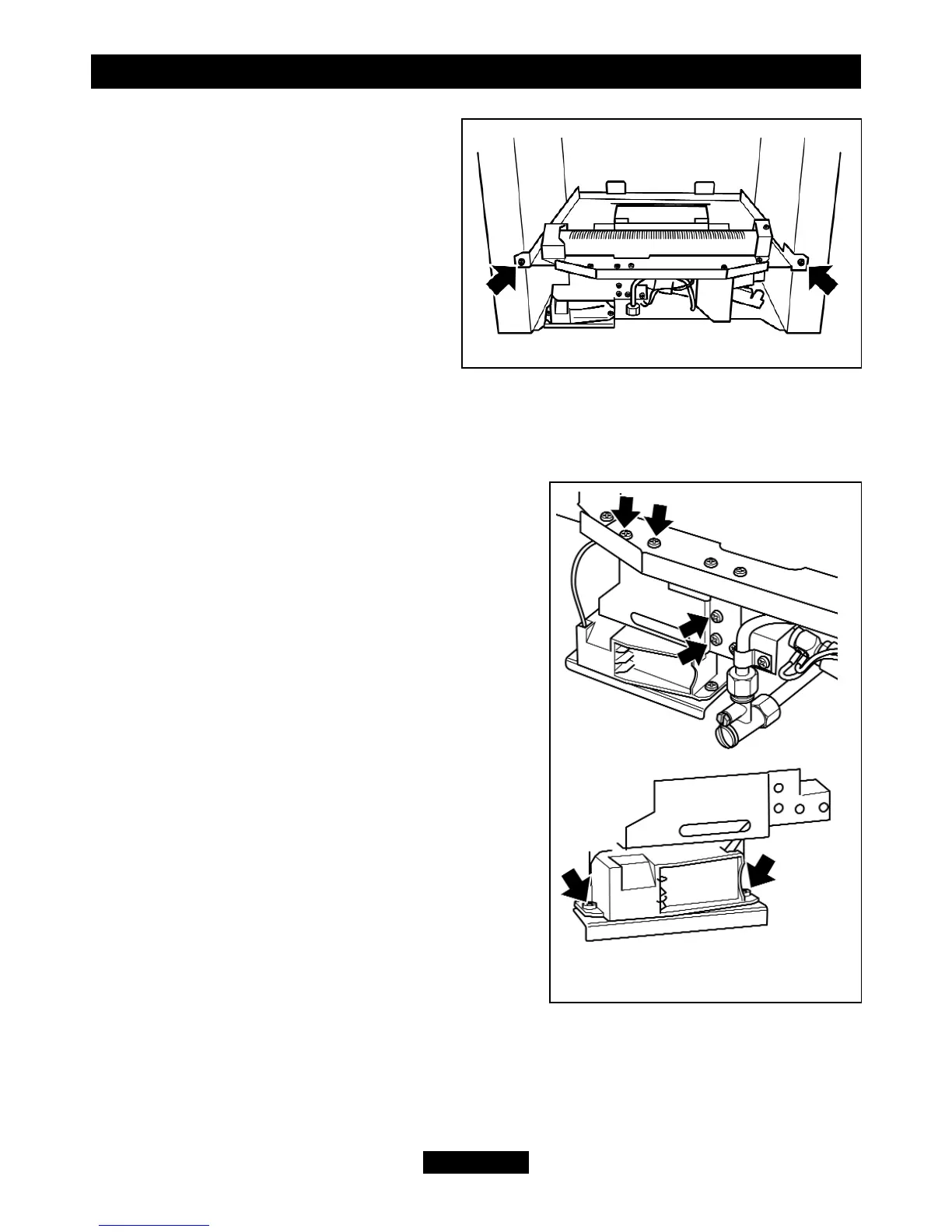
4. Detach the burner unit from the
convection box by removing two screws
(See figure 54).
5. Replace in the reverse order.
17.8 To remove the electronic ignition generator.
1. Remove the bottom front and fire front castings.
For ‘Adorn’ and ‘Icon’ models remove the fascia
(See section 17.4).
2. Remove the ceramic fuel effect.
3. Remove the battery.
4. Remove the spark lead.
5. Unscrew the four support bracket screws (See
figure 55). The generator and its support bracket
can now be moved forward. Be careful not to
apply tension to the microswitch leads.
6. Remove the two fixing screws that attach the
generator unit to the support bracket. The igniter
generator can now be removed (See figure 55)
7. Remove the two leads to the switch and remove
the spark lead. If necessary, mark them to ensure
that they are replaced on to the correct terminals.
8. Replace the generator
9. Refit in the reverse order.
17.9 To remove the thermocouple interrupter
block.
(See figure 48).
1. Remove the burner unit (See section 17.7).
2. Detach the thermocouple from the interrupter block by unscrewing the
thermocouple nut.
3. Detach the two microswitch leads from the interrupter block.
4. Remove the interrupter block by unscrewing from the gas shut-off tap.
© GDC Group Ltd. 2011
Page 44
INSTALLER GUIDE
Figure 54. Burner attachment points
Figure 55. Removal of
electronic generator