3. Detach the pilot pipe from the pilot unit.
4. Detach the thermocouple from the gas valve
5. Detach the electrode lead from the rear of the
piezo spark generator on the gas valve.
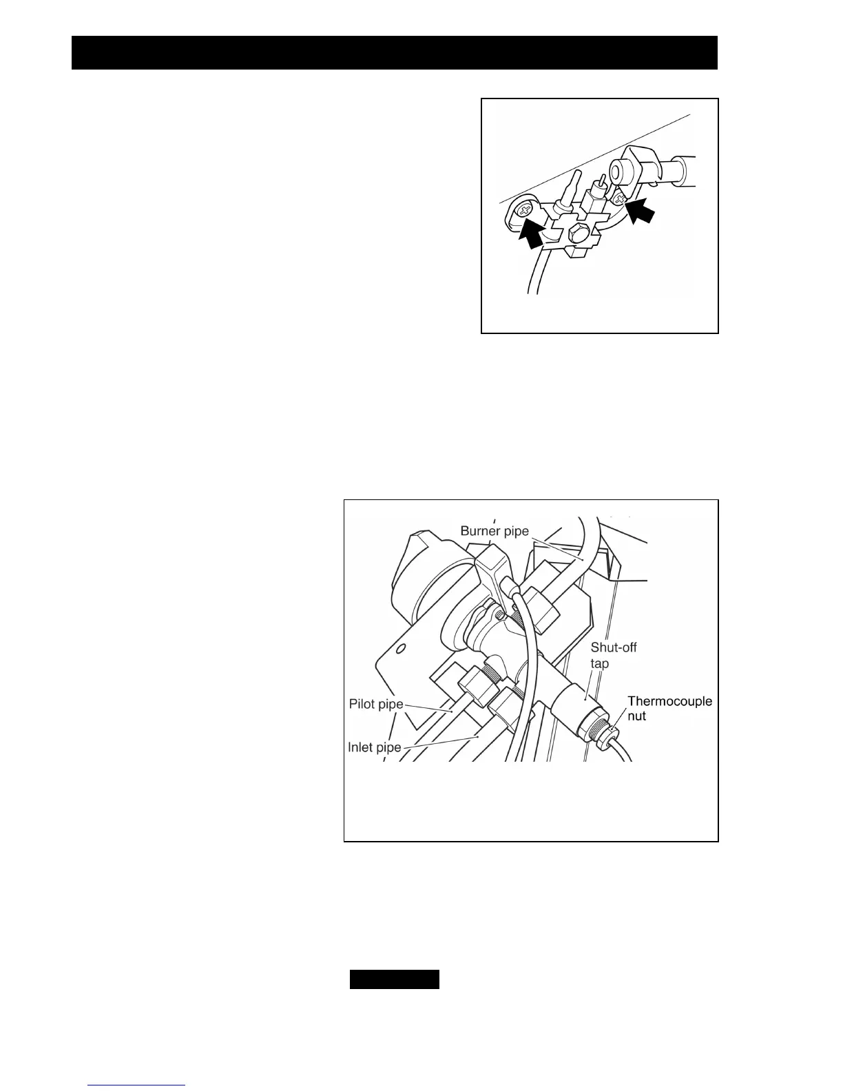
6. Remove the two screws securing the pilot unit (See
figure 30).
7. Refit in the reverse order.
Note: The pilot unit is an atmosphere sensing device.
It must be replaced as a whole assembly. Its
individual components are not separately replaceable.
16.4 To remove the gas valve.
(See figure 31).
1. Remove the burner unit (See section 16.2).
2. If lying the burner on its back, ensure that the work surface is suitably protected
This will avoid damage to the work surface. Turn the burner unit upside down.
3. Detach the pilot pipe from the gas valve.
4. Detach the inlet pipe.
5. Detach the injector pipe.
6. Detach the electrode lead from the rear of the piezo spark generator on the gas
valve.
7. Remove the control knob by
pulling forward.
8. Remove the thermocouple by
unscrewing the thermocouple nut at
the gas valve.
9. Remove the hexagonal nut
securing the gas valve to the
mounting bracket.
10. Remove the gas valve.
11. Refit in the reverse order.
16.5 To remove the burner.
(See figure 32).
1. Remove the burner unit (See
section 16.2).
2. Support the elbow injector and unscrew the injector nut.
3. Remove the two screws from the burner clamping plate (See figure 32).
4. Lift the right hand side of the burner, slide it to the right and lift clear
5. Refit in reverse order.
Page 36
© GDC Group Ltd 2014