15.3 TO REMOVE THE FIRE FRONT
15.3.1 “Adorn” Front
15.3.1.1 Remove the bottom front cover
casting.
15.3.1.2 Detach the control linking bar from the
control pivot bracket by removing the
knurled screw (See fig. 34).
15.3.1.3 Remove the two screws securing the
bottom of the casting to the sides of
the convection box (See fig.29).
15.3.1.4 Make sure that the control linking bar
has been detached (see 15.3.1.2).
Carefully lift the casting upwards to
clear the upper retaining brackets on
the convection box (See fig. 28). Pull
the casting clear and place carefully
aside.
15.3.1.5 Refit in the reverse order. Make sure
that the casting is properly located
over the upper retaining brackets. See
section 10 of this manual for detailed
fitting instructions.
15.3.2 “Visage” Front
15.3.2.1 Remove the bottom front cover
casting.
15.3.2.2 Lift the fire front casting up and
forward to release the locating screw
heads at the back of the casting from
the keyholes in the surround sides
(See fig. 44). Lift the casting clear.
15.3.2.3 Detach the control linking bar from the
control pivot bracket by removing
the knurled screw (See fig. 34).
15.3.2.4 Remove the two screws securing the
bottom of the front surround to the
sides of the convection box (See fig. 31).
15.3.2.5 Make sure that the control linking bar
has been detached (see 15.3.2.3).
Carefully lift the surround unit
upwards to clear the upper retaining
brackets on the convection box (See
fig. 30). Pull the surround clear and
place carefully aside.
15.3.2.6 Refit in the reverse order. Make sure
that the surround is properly located
over the upper retaining brackets. See
section 10 of this manual for detailed
fitting instructions.
15.3.3 “Icon” Front
15.3.3.1 Detach the bottom front cover by
removing the two knurled screws (See
fig. 45).
15.3.3.2 Detach the control linking bar from the
control pivot bracket by removing the
knurled screw (See fig. 34).
15.3.3.3 Remove the two screws securing the
bottom of the front surround to the
convection box (See fig. 33).
15.3.3.4 Make sure that the control linking bar
has been detached (see 15.3.3.2).
Carefully lift the surround unit
upwards to clear the upper retaining
brackets on the convection box (See
fig. 32). Pull the surround clear and
place carefully aside.
15.3.3.5 Refit in the reverse order. Make sure
that the surround is properly located
over the upper retaining brackets. See
section 10 of this manual for detailed
fitting instructions.
15.4 TO REPLACE THE CONTROL SLIDE
BUTTON (“VISAGE “ & “ICON” ONLY)
15.4.1 Remove the front unit - See section 15.3
15.4.2 Detach the rear shield plate by
removing two screws (“Visage”) or
four screws (“Icon”) from the rear
right side of the front surround (See
fig. 49).
15.4.3 Remove the two screws securing the
slide button to the back of the slide
mechanism bar. Raise the button to
Page 24
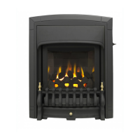
figure 48 Thermocouple interrupter block
INSTALLER GUIDE
 Loading...