clear the bar and pull through the slot
in the surround side (See fig. 49).
15.4.4 Refit in the reverse order.
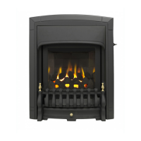
15.5 TO REMOVE THE CONTROL SLIDE UNIT
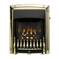
15.5.1 “Visage” & “Icon
”
15.5.1.1 Remove the surround unit and slide
button - see section 15.4
15.5.1.2 Remove two screws securing the
plastic slide mechanism box to the rear
side of the front casting. Lift the slide
unit clear.
15.5.1.3 Refit in the reverse order.
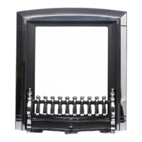
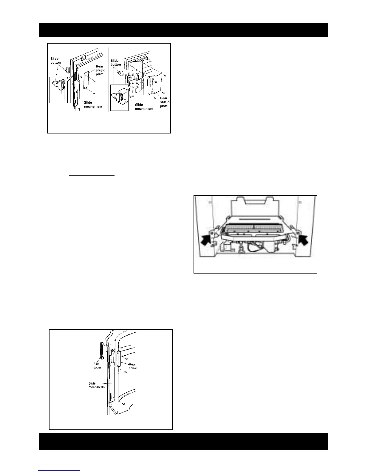
15.5.2 “Adorn
”
15.5.1 Remove the front casting - See section
15.3
15.5.1 Detach the slide side cover and rear
shield by removing two screws from
the rear upper side of the front casting
(See fig. 50).
15.5.2 Remove two screws securing the
plastic slide mechanism box to the rear
side of the front casting (See fig. 50).
Lift the slide unit clear.
15.5.4 Refit in the reverse order.
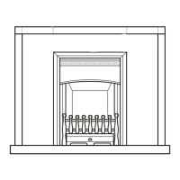
15.6 TO REMOVE THE BURNER UNIT
(See figure 51)
15.6.1 Remove the front surround unit- See
section 15.3.
15.6.2 Remove the 11 loose coals, the front
coal and the base coal.
15.6.3 Remove the ceramic side and rear
walls. Note whether the sidewalls are
fitted with the brick pattern or plain
surface visible so that they can be
replaced in the same manner.
15.6.4 Support the inlet isolating elbow to
avoid straining the pipework and
disconnect the appliance from the
elbow.
15.6.5 Detach the burner unit from the
convection box by removing 2 screws.
15.6.6 Replace in the reverse order.
15.7 TO REMOVE THE ELECTRONIC
IGNITION GENERATOR
15.7.1 Remove the bottom front and fire front
castings and front surround - see
section 15.3.
15.7.2 Remove the battery.
15.7.3 Remove the burner unit ñ see section
15.6.
15.7.4 Remove the two leads to the switch
and remove the spark lead, marking
them if Necessary to ensure that they
are replaced on to the correct
terminals.
15.7.5 Remove the two fixing screws that
attach the generator unit to the bracket.
The igniter generator can now be
exchanged.
Page 25
figure 49 Control slide unit- “Visage” & “Icon”
figure 50 Control slide unit- “Adorn”
figure 51 Burner removal points
INSTALLER GUIDE
 Loading...