INSTALLER’S GUIDE
Page 44
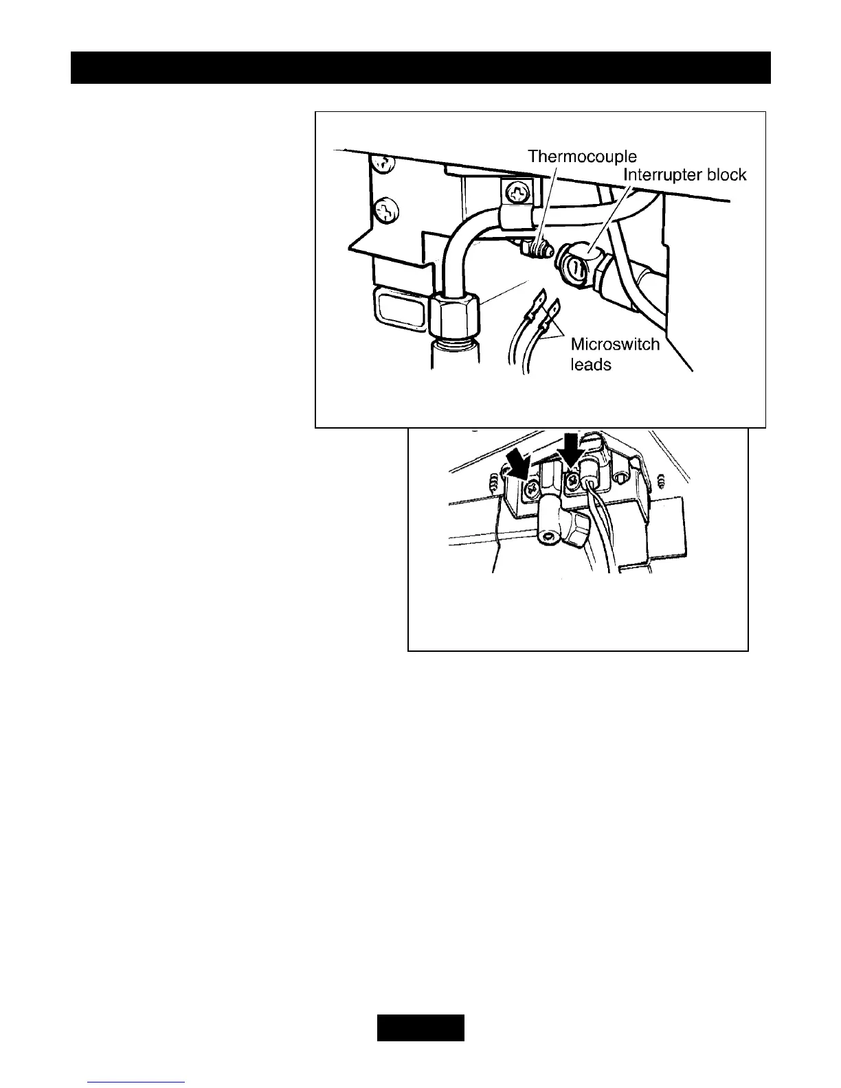
Figure 60. Pilot unit removal
(Dust cage not shown for clarity)
Figure 59. Thermocouple interrupter block
4. Remove the interrupter
block by unscrewing from the
gas shut-off tap.
5. Refit in the reverse order.
If the microswitch leads
cannot be easily attached to
the interrupter block when it
is fully tightened to the gas
shut-off tap, slacken it and
rotate to allow the leads to be
fitted. Retighten making sure
that the leads remain in place
in the interrupter block. Fit
and tighten the thermocouple
nut making sure that the leads
are secured in the interrupter block to
give a good electrical contact.
16.10 To Remove the Pilot Unit
7. Remove the burner unit - See section
16.6.
8. If lying the burner on its back,
unscrew and remove the two ceramic
support brackets from the top of the
burner unit. This will avoid damage to the
brackets and the worksurface (see figure 57)
9. Detach the pilot pipe from the gas shut-off tap.
10. Detach the thermocouple from the interrupter block by unscrewing the thermocouple
nut.
11. Detach the electrode lead from the underside of the electrode tab.
12. Remove the first screw securing the dust cage to the pilot unit & burner. Carefully
remove the dust cage and place aside. See figure 60.
13. Remove the second screw securing the pilot unit to the burner. Remove the pilot unit
and place it aside. See figure 60.
14. Disconnect the pilot pipe from the pilot unit elbow.
15. Refit in the reverse order.
Note: 1. The pilot unit is an atmosphere sensing device. It must be replaced as a
whole assembly. Its individual components are not separately replaceable.