APPENDIX
F
Serial Data Output
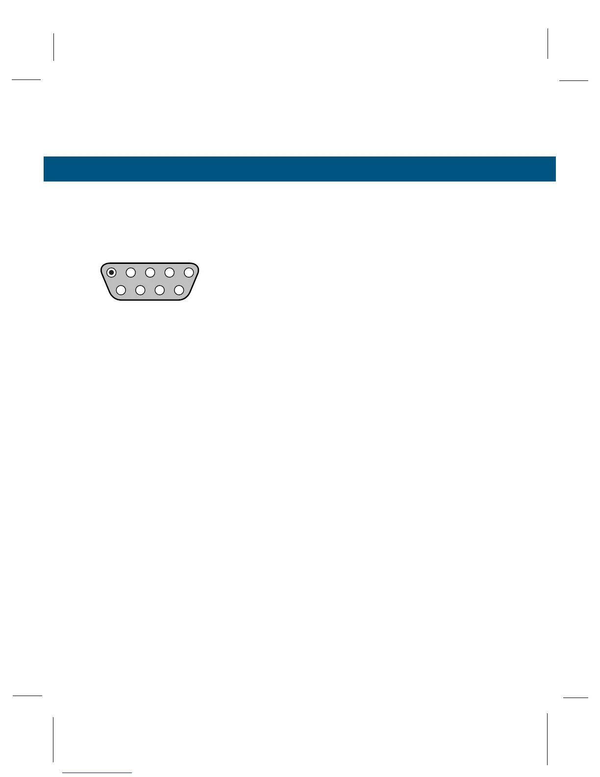
Pin Diagram:
Pin # Mnemonic Description
1 DCD Data Carrier Detect (output)
2 RXD Receive Data (output)
3 TXD Transmit Data (input)
4 N/C No Connection
5 GND Signal Ground (passive)
6 DSR Data Set Ready (output)
7 RTS Request to Send (input)
8 CTS Clear to Send (output)
9 N/C No Connection
DSR is tied true whenever the instrument power is on. DCD and
CTS are internally tied together.
The serial port is configured as Data Communications Equipment
(DCE). This enables the osmometer to be connected directly to
most computers and printers which are usually configured as Data
Terminal Equipment (DTE). Use a STANDARD PC-AT type 9-pin to
25 pin serial cable. Do not use a null-modem cable unless your
device is configured as DCE.
Data output is in ASCII characters. Upon power-up the osmometer
will output the characters "READY" at the serial port. At the comple-
tion of a sample assay the instrument looks for RTS to be true. If
this line is high, "ENTER to send" is displayed on the top line of the
display. Press ENTER at this time to output the data on the serial
port. The data format is as follows:
20 hex (space)
Reading
"mmol/kg"
OA hex (line feed)
OD hex (carriage return)
94