20
ISTRUCTIONS FOR THE USE AND MAINTENANCE - JB / JD
Coupling
type
08 S
10 S
10 SS
11 S
14 S
Max.
speed
(RPM)
Cont.
duty
Intermittent
duty
4500
4000
4000
3500
2800
17
31
31
48
94
2
30
30
62
121
Max. torque dNm
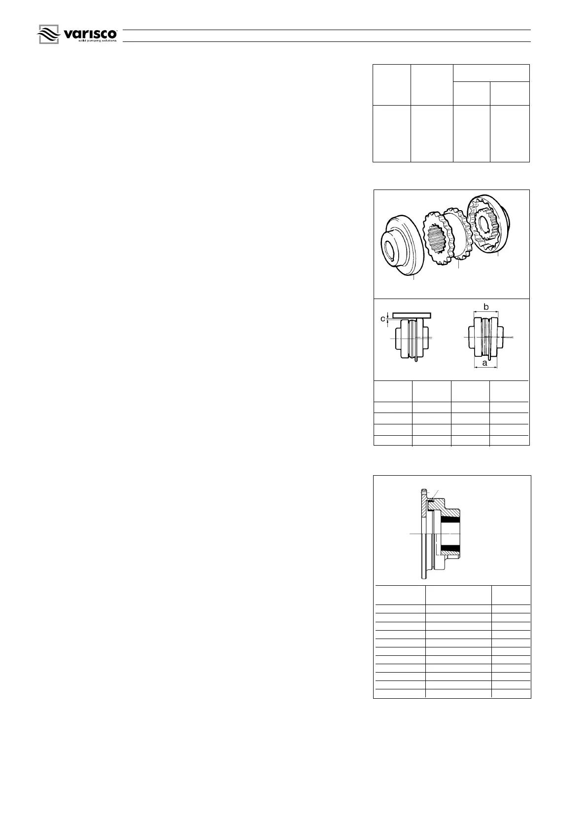
fig. 27
Half coupling
Half coupling
Rubber collar
Coupling
type
C
mm
(b-a)
mm
Torque
N m
J4
0,25 1,1 10
J5
0,4 1,4 20
S6
0,4 1,8 40
S7
0,5 2,1 70
fig. 28
rubber dowel
Coupling
type
Max. torque kgm rpm
14
15 4800
20
25 4400
27
40 4100
40
60 3500
55
80 3300
88
110 3000
110
150 2700
145
190 2500
180
240 2200
250
300 2150
330
400 2000
12.10 Replacing the TWIN-DISC coupling blocks (RBD series)
- Remove the pump from its seat
- Remove the worn blocks and replace them with new ones
- Check the state of wear of the aluminium flange
- Couple the pump to the engine
- Maximum alignment error: 0.7 mm
- When ordering spare rubber blocks, specify the shaft diameter and the type of
coupling.
12.11 Replacing the rubber collar of SURE-FLEX couplings (fig. 27)
- Unscrew the anchor bolts at the base of the pump or engine and separate the two
halves of the coupling
- Remove the worn rubber collar and replace it with a new one. In the case of two
piece rubber collars (type S) leave the steel ring free to move in one of the two
grooves near the indentation
- Move the pump towards the engine and fit the indentation of the half coupling to that
of the rubber collar
- Close the coupling leaving an axial play of 2 mm max. for type J couplings and
3 mm max. for type S couplings
- Check the radial and angular alignment as follows:
- Radial: (fig. 27) with a ruler placed on the outer surface of the half couplings, measure
the maximum misalignment (dimension C) in at least four points around the circum-
ference and try to bring it as close as possible to zero (see table).
- Angular: (fig. 27) with a gauge, measure at a minimum of four points the distance
between the two halves of the coupling and bring the difference (b-a) as close as
possible to zero (see table).
- Tighten the anchor bolts at the base of the pump and motor.
- When ordering spare parts, specify the type of coupling (stamped on the inside of
the half couplings) and the shaft diameter.
12.12 Replacing the rubber dowels of flexible couplings (GBF) (fig. 28)
- Unscrew the anchor bolts at the base of the pump or engine and separate the two
halves of the coupling
- Remove the worn dowels and replace them with new ones, fixing them in place with
a little adhesive
- Move the pump towards the engine until the coupling is completely closed, then draw
it back by 2-3 mm to separate the two halves of the coupling
- Tighten the bolts which anchor the pump and engine to the base plate
- When ordering dowels, specify the diameter of the shaft and the type of coupling
.
13 OPERATING PROBLEMS: CAUSES AND REMEDIES
Attention: before examining the possible causes of operating problems, ensure
that all control instruments (vacuum gauge, pressure gauge, revolution counter,
flow recorder etc.) are working correctly.
13.1 The pump does not prime
1 The pump casing is empty or non sufficiently full
fill the pump casing through the priming cover or plug (fig. 17)
2 The liquid inside the pump casing is overheated
add cold liquid to the pump casing through the priming cover or plug (fig. 17)
3 Air leaks in the joints or cracks in the suction line
Check that couplings and clamps are tight and inspect the suction line
4 Delivery line under pressure
bleed the delivery line
5 Low rotation speed of the pump
increase the speed only after having verified the contract data and the pump
performance curve
6 The impeller is worn or broken
check the state of the impeller through the impeller inspection cover, or remove the
pump casing as described in paragraph 12.2
7 The cutwater (leading edge of the volute) is worn
remove the casing as described in paragraph 12.2. Add material to the cutwater by
welding, and smooth it to restore the original profile. If the cutwater is badly worn,
replace the casing.
8 The suction strainer (if fitted) is clogged
remove the obstructions
9 The suction lift is too high
reduce the suction lift
10 Air enters through the mechanical seal
disassemble the seal and clean it (see paragraph 12.5); if the problem persists,
change the seal
11 The impeller is clogged by foreign objects
disassemble the casing and remove the foreign objects.
 Loading...