LVP615S#3
LOOP
LVP615S#2
LOOP
LVP615S#4
LOOP
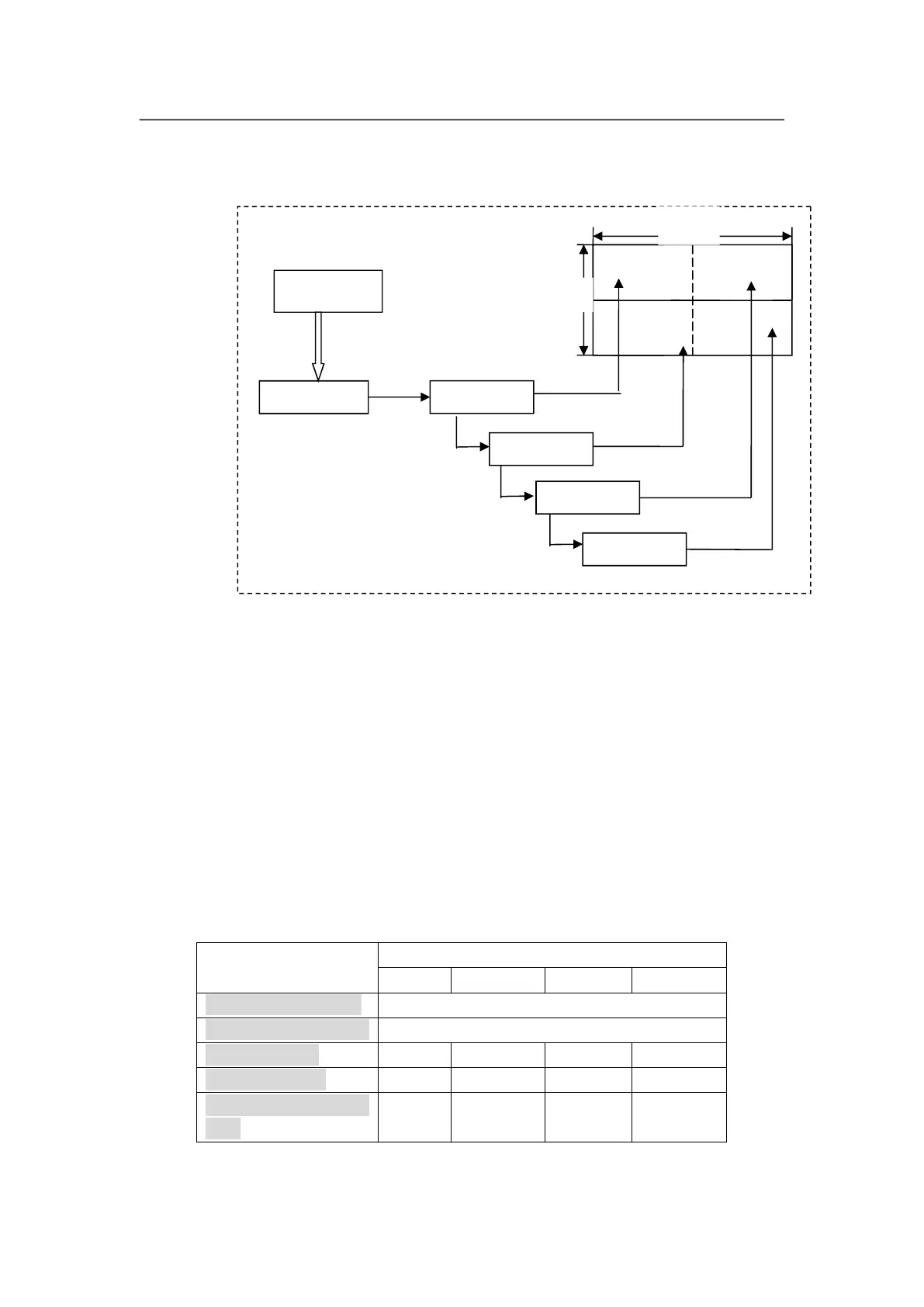
As above diagram shows, all input signals are connected to and switched by
#0 LVP615S. The 2 same DVI outputs of #0 LVP615S are connect to #1
LVP615S and #2 LVP615S. Then DVI loop to #3 and #4.
After that, the output signal of #0 LVP615S is cropped and scale up in #1
LVP615S, #2 LVP615S, #3 LVP615S and #4 LVP615S.
Finally the image that they output will be finally displayed as a whole picture on
4 pieces of LED screens.
The parameters of the 4 units of LVP615S are as below:
Parameter setups of processor