29
30
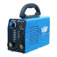
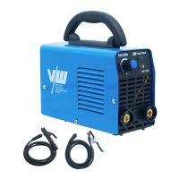
2.1 Brief introduction
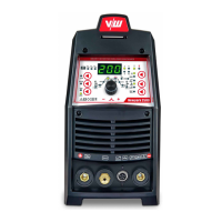
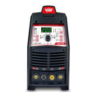
ARC 200G / ARC 200K welding machines adopts the latest pulse width modulation (PWM)
technology and insulated gate bipolar transistor (IGBT) power module, which can change work
frequency to medium frequency so as to replace the traditional hulking work frequency
transformer with the cabinet medium frequency transformer. Thus its characterized with
portable, small size, light weight, low consumption and etc.
2.2 Working principle
230V
The working principle of ARC 200G / ARC 200K welding machines is shown as the
following figure. Single-phase 230V work frequency AC is rectified into DC(about 312 V),
then is converted to medium frequency AC (about 20-40KHz) by inverter device (IGBT
module), after reducing voltage by medium transformer (the main transformer) and rectifying
by medium frequency rectifier (fast recovery diodes),then is outputted DC .The circuit adopts
current feedback control technology to insure current output stably. Meanwhile, the welding
current parameter can be adjusted continuously and steplessly to meet the requirements of
welding craft.
Specification
Welding current
2. 3 Welding electrodes specifications
Adjust knobs of welding current , make welding current is adequate to welding electrode
according with as following:
φ2.5
φ3. 2
φ4. 0 φ5. 0
70-100A
110-140A 170-230A 230-280A
2.5 Specifications
Nominal Supply Voltage
Nominal Supply Frequency
Welding Current Range
Single Phase Generator Requirement
Welding Output, 40ºC, 10 min.
Open circuit voltage
Protection Class
Maximum Input Current
Effective Input Current
Due to variations that can occur in manufactured products, claimed performance, voltages,
ratings, all capacities, measurements, dimensions and weights quoted are approximate
only. Achievable capacities and ratings in use and operation will depend upon correct
installation, use, applications, maintenance and service.
10 - 200A
16A
35.8A
14.4KVA
200A @ 20%, 28V 89A @ 100%,23.6V
IP23
Description
Weight
Power Source Dimensions
Cooling
Welder Type
European Standards
Number of Phases
Fan Cooled
Inverter Power Source
EN 60974-1 / IEC 60974-1
1
230V +/- 15%
50/60Hz
62V DC
NOTE
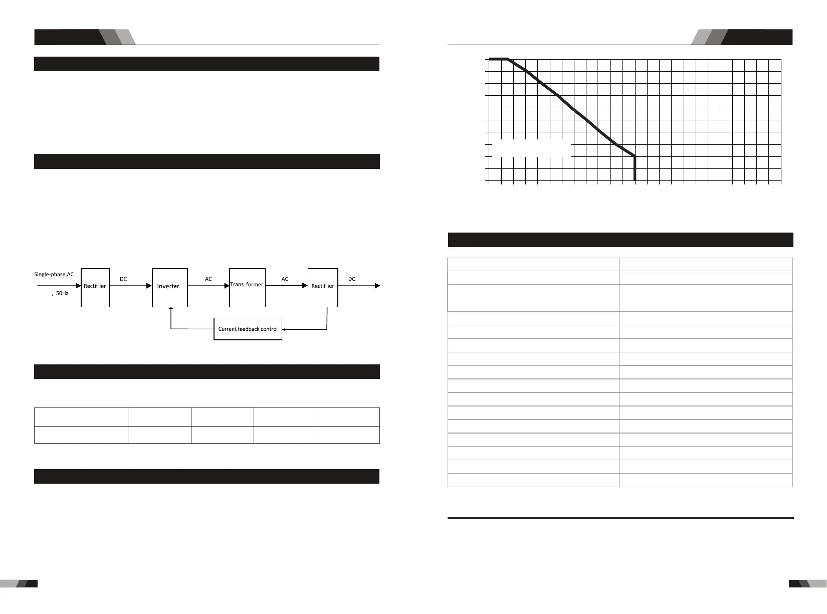
2.4Duty cycle
The rated duty cycle of a Welding Power Source is a statement of the time it may be
insulation of the component parts. To explain the 10 minute duty cycle period the following
example is used. Suppose a Welding Power Source is designed to operate at a 20% duty
cycle, 200 amperes at 28 volts. This means that it has been designed and built to provide
the rated amperage (200A) for 4 minutes, i.e. arc welding time, out of every 10 minute
the Welding Power Source must idle and be allowed to cool.
operated at its rated welding current output without exceeding the temperature limits of the
period (20% of 10 minutes is 4 minutes). During the other 6 minutes of the 10 minute period
SummarySummary
ARC SERIES EQUIPMENTARC SERIES EQUIPMENT
Duty Cycle(PERCENTAGE)
Welding Current(AMPS)
10 0 12 0 14 0 16 0 1 8 0 20 0 22 0
0
10
20
30
40
50
60
70
80
90
10 0
24 0 26 0 28 0 3 0 0 3 2 00
Sicherer Arbeitsvorgang
(STICK)
ARC 200G / ARC 200K
2.4kg & 2.5kg
H225mmxB97mmxT170mm
H235mmxB110mmxT175mm