Operation
Operation
59
60
3.5 Setup for cutting (CT 520PD)
In order for the unit to function correctly, it must be installed properly. Follow the procedure
given below for correct installation:
1. Read the safety rules given in this manual carefully.
CAUTION
Do not point the torch jet at foreign bodies.
13. Once cutting is over, release the torch button to put out the arc. A period of post-flow
time 45 to 75 seconds (required for torch cooling) will follow. Do not disconnect air
until this cooling period has been completed. Failure to do this will result in torch head
damage.
12. Contact the copper tip of the torch to the work piece, press the button of the forch until
the cutting operation.
the arc-starting and raise the cutting torch about 1mm above the work piece, and perform
2. Check on receiving the unit that there are no defective parts or parts damaged during
transportation.
3. Set your unit up in an area which is adequately ventilated and make sure that the air vents
are not obstructed.
4. Connect the power supply cable to a socket located as near as possible to the work area,
so that the unit can be switched off quickly in case of emergency.
5. Your machine has a 16 amp plug fitted, before use check that the green/yellow earth is
connected to the earth pin socket of fitted plug.
6. Make sure that the mains supply switch and any fuses have a value which ± 15% the
maximum current absorbed by the unit. All fuses should be the slow-blow type.
7. Any extensions of power supply cable should have the same cross-section as the power
supply cable. The extension leads, however, should only be used when absolutely
necessary. It is important to note that any extension of mains cables or torch cables will
possibly affect the cutting performance of this cutting equipment, due to the fact that the
resistance of the cable will reduce voltage input, which is determined by the length of the
cable. The supplied length of main cables and torch cables is recommended.
8. Fasten the earth clamp to the piece to be cut, If the surface of the piece to be cut is painted,
rusty or covered with insulating material, clean the surface so that satisfactory contact
between the piece and the earth clamp can be obtained.
9. Make sure that the torch has been assembled with the correct components and that the
cutting tip is suitable for the cutting current.
10. Connect air to regulator and adjust regulator to deliver 5-6 bar 90ltr/min
11. Switch the unit on using the main switch located on the back side.
CAUTION
Avoid unnecessary lighting of the pilot arc to prevent excessive
consumption of the electrode and nozzle.
Air regulator installation and operation
1. Firmly tight and seal the copper air hole at IN and OUT terminal by high pressure rubber
tube .
2.Tight and seal the meter with meter face rubber tube.
3.Fix the connecting shelf with screw as the regulator position.
4.Get down the plastic screw and fix the regulator on the shelf.
5.Turn on the air valve, turn up the pressure adjusting knob, turn the pressure volume (meter
inside shows kg), and then put down the knob.(+ means increasing pressure, - means
decreasing pressure.)
6.Scale of the meter is as follow. The volume in the picture is 6 kg.
7. If the water in thegas filtering bottle is too much, please turn on the water valve to let the
water go out.
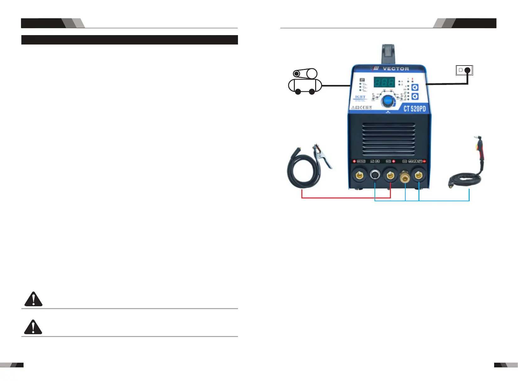
power supply
Air compressor
Plasma torch
Earth Clamp
DC TIG SERIES EQUIPMENTDC TIG SERIES EQUIPMENT