15
16
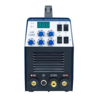
Operation
Operation
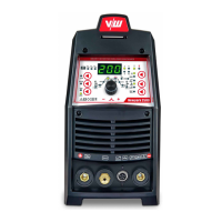
1. Digital Ammeter / Parameter meter
The digital Ammeter is used to display the actual output current of the power source. It is
also used to display Parameters in Programming Mode.
Depending on the Programming Parameter selected, the status indictor adjacent to the
Ammeter will illuminate to show the units of the programming parameter.
When welding, the Ammeter will display actual welding current.
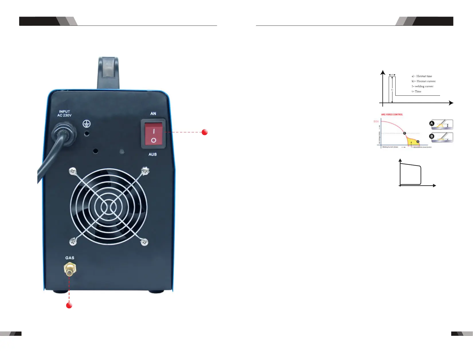
2. Hot Start
Arcforce Correction
Hot Start Function reliably ignites the electrode
and melts perfectly to ensure the best quality
even at the start of the seam. this solution makes
lack of fusion and cold welds a thing of the past
and significantly reduces weld reinforcement.
Adjust the hot start current here and the time here.
During the welding process, arcforce prevents
th e e l e c t r o d e s t i ck i n g i n t h e w el d p o o l w i t h
increases in current. this makes it easier to weld
large-drop melting electrode types at low current
strengths with a short arc in particular.
I
t
Anti-stick prevents the electrode from annealing.
If the electrode sticks in spite of the arcrorce device, the
machine automatically switches over to the minimum
current within about 1 second to prevent the electrode
from overheating. In order to easily separate the
electrode and electrode holder to protect the welder.
Antistick
Antistick
U
I
3. Time Indicator (s)
Time indicator , when setting programm in gas pre-flow, up slope, down slope and gas
post-flow, this indicator will be on.
4. Current Indicator
When setting programm in the peak current, base current, ending current and rem , this
current indicator will be on.
6. Thermal Overload Indicator Light
This welding power source is protected by a self resetting thermostat. The indicator will
illuminate if the duty cycle of the power source has been exceeded. Should the thermal
overload indicator illuminate the output of the power source will be disabled. Once the
power source cools down this light will go OFF and the over temperature condition will
automatically reset. Note that the mains power switch should remain in the on position
such that the fan continues to operate thus allowing the unit to cool sufficiently. Do not
switch the unit off should a thermal overload condition be present.
5. Power ON Indicator
The POWER ON indicator illuminates when the ON/OFF switch is in the ON position and
the correct mains voltage is present.
7. Trigger Mode Control Button (HF TIG and LIFT TIG Mode only)
The trigger mode control is used to switch the functionality of the torch trigger between
2T and 4T.
2T Normal Mode In this mode, the torch trigger must remain pressed for thewelding
output to be active.
DC TIG SERIES EQUIPMENTDC TIG SERIES EQUIPMENT
51
52