EMR
3
Setup and Operation Manual C&C Mode Setup Categories
39
METER CALIBRATION
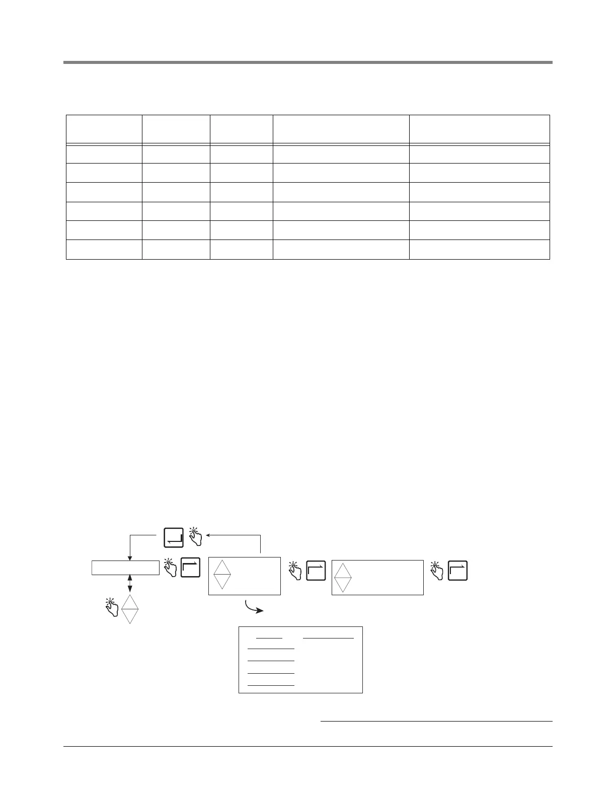
Figure 41 illustrates Meter Calibration setup in C&C Mode.
Figure 41. Meter Calibration Setup
7 7.2 45 522.0 594.0
8 15.0 59 510.0 585.0
9 23.9 75 496.0 574.0
10 29.4 85 487.0 568.0
11 35.0 95 478.0 562.0
12 40.6 105 469.0 555.0
2
For other liquefied gases modify the density defaults to their proper values in accordance with ASTM-IP Tables.
3
The EMR
3
calculates temperature compensated volume using the 12 density pairs from Table 4 above in the following
formula:
V
o
= V
t
(ρ
t
/ ρ
o
)
where: V
t
= uncompensated gross volume
V
o
= calculated temperature compensated volume
ρ
t
/ ρ
o
= ratio of density at measured temperature to density at base temperature
The ratio of density is calculated after inserting the appropriate P constants into the equation below:
ρ
t
/ ρ
o
= 1 + (-P
1
/ ρ
o
+ P
2
)(t - 15°C) + (-P
3
/ ρ
o
+ P
4
)(t - 15°C)
2
Notes:
The ratio of density is equation 4.21 from page 10 of the PTB-A 5 Measuring Systems for Liquids other than Water - June 1999 edi-
tion.
Setting factors (P
1
, P
2
, P
3
and P
4
) used to calculate ρ
t
/ ρ
o
above are taken from Table 4.3 on page 11 of the PTB-A 5 Measuring Sys-
tems for Liquids other than Water - June 1999 edition.
Table 5 - 12 Temperature/Density Pairs
2,3
Entry No. Temp (°C) Temp (°F)
Propane Density (Default)
(kg/m
3
)
Butane Density (Reference)
(kg/m
3
)
CONFIGURE I/O
OEM MESSAGE
DELIVERY OPTIONS
REPORT FORMATS
RESTART
SECURITY CODE
LANGUAGE
DISPLAY SYNTAX
TEMPERATURE
FUEL SOURCE
PROD CAL 1
PROD CAL 2
PROD CAL 3
PROD CAL 4
+
-
+
-
+
AUTO CALIBRATE
MULTICALIBRATE
MANUAL CALIBRT
+
-
+
Press the up/down
buttons to cycle
through remaining
C/C Mode categories
NEXT
ENTER
NEXT NEXT
METER CALIBRTN
Press ENTER to accept any changes in any column -
and/or continue pressing to return to METER CALIBRTN
See Meter
Calibration
figures for each
selection's setu
Product Prod Cal Number
PROD CAL 1
PROD CAL 2
PROD CAL 3
PROD CAL 4
Write in the products used in
each of the four calibrations