16
6 Setup
VEGAPOINT 11 • Transistor with IO-Link
63008-EN-200527
6 Setup
6.1 Indication of the switching status
The switching status of the electronics can be checked via the signal
lamps (LEDs) integrated in the upper part of the housing.
The signal lamps have the following meaning:
•
Green lights up - power supply connected, sensor output high-
impedance
•
Greenashing-Maintenancerequired
•
Yellow lights up - power supply connected, sensor output low
impedance
•
Redlightsbriey-functiontestduringinstrumentstart(for0.5s)
•
Red lights - shortcircuit or overload in the load circuit (sensor
output high-impedance)
•
Redashes-Erroronthesensorortheelectronics(sensoroutput
high impedance)
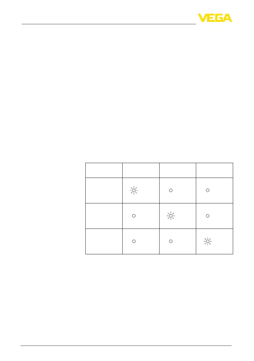
6.2 Function table
The following table provides an overview of the switching conditions
depending on the set mode and the level.
Switching status
Output
Control lamp
Yellow
Control lamp
Green
Control lamp
Red
closed
open
Fault