3
4
5
1
2
+
( )
(-)
1
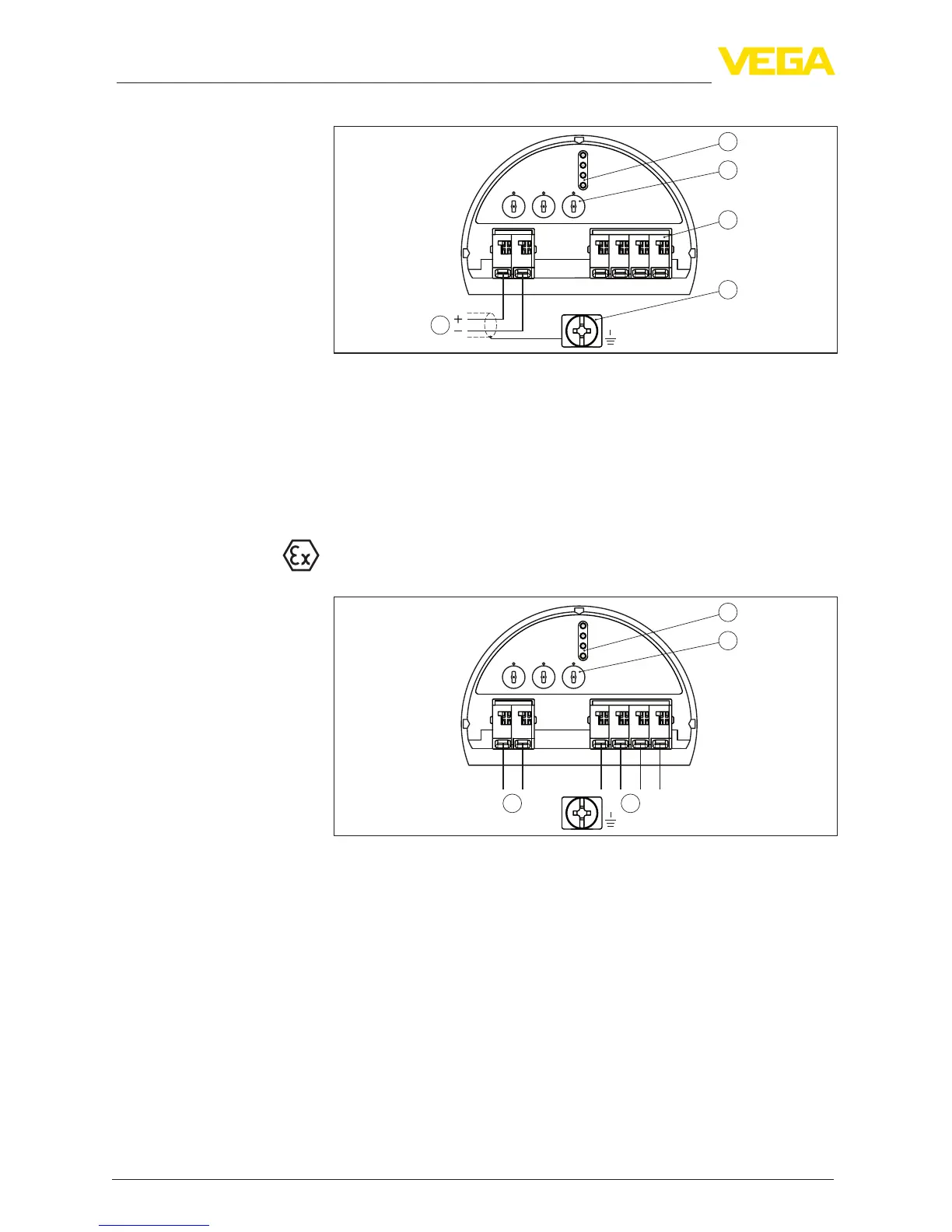
Fig. 25: Electronics and terminal compartment - single chamber housing
1 Voltage supply, signal output
2 For display and adjustment module or interface adapter
3 Selection switch for instrument address
4 For external display and adjustment unit
5 Ground terminal for connection of the cable screen
5.4 Wiring plan, double chamber housing
The following illustrations apply to the non-Ex as well as to the Ex-ia
version.
11
5
00
5
1
6
2
7
3
8
4
9
0
5
1
6
2
7
3
8
4
9
1
0
1
678
Bus
3
1
2
+
( )
(-)
Fig. 26: Electronics compartment - double chamber housing
1 Internal connection to the terminal compartment
2 Contact pins for the display and adjustment module or interface adapter
3 Selection switch for bus address
Electronics and terminal
compartment
Electronics compartment