37
6 Set up with the display and adjustment module
VEGAPULS 67 • Probus PA
36533-EN-170405
1 2
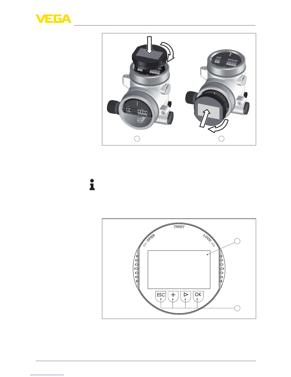
Fig. 37: Installing the display and adjustment module in the double chamber
housing
1 In the electronics compartment
2 In the terminal compartment
Note:
If you intend to retrot the instrument with a display and adjustment
module for continuous measured value indication, a higher lid with an
inspection glass is required.
6.2 Adjustment system
1
2
Fig. 38: Display and adjustment elements
1 LC display
2 Adjustment keys
•
[OK] key:Key functions