13
4 Mounting
VEGAPULS C 21 • Modbus and Levelmaster protocol
58343-EN-200806
nent. By turning the instrument in the mounting strap, the polarisation
canbeusedtoreducetheeectsoffalseechoes.
The position of the polarisation is in the middle of the type label on the
instrument.
1
Fig. 6: Position of the polarisation
1 Middle of the type label
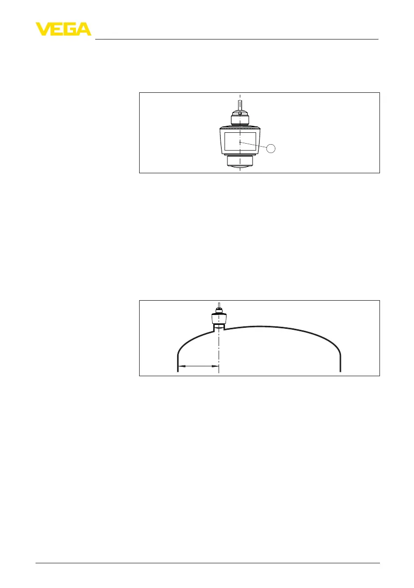
When mounting the device, keep a distance of at least 200 mm
(7.874 in) from the vessel wall. If the device is installed in the center
of dished or round vessel tops, multiple echoes can arise. However,
these can be suppressed by an appropriate adjustment (see chapter
" Setup").
If you cannot maintain this distance, you should carry out a false
signal suppression during setup. This applies particularly if buildup on
the vessel wall is expected. In such cases, we recommend repeating
the false signal suppression at a later date with existing buildup.
> 200 mm
(7.87
")
Fig. 7: Mounting of the radar sensor on round vessel tops
In vessels with conical bottom it can be advantageous to mount the
device in the centre of the vessel, as measurement is then possible
down to the bottom.
Installation position