14
4 Mounting
VEGAPULS C 21 • Modbus and Levelmaster protocol
58343-EN-200806
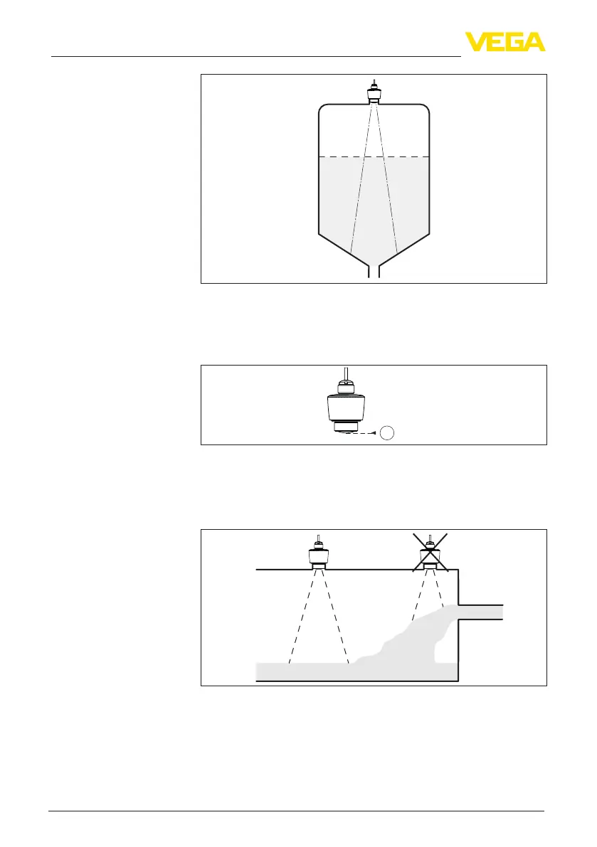
Fig. 8: Mounting of the radar sensor on vessels with conical bottom
The centre of the antenna lens is the beginning of the measuring
range and at the same time the reference plane for the min./max.
adjustment, see following diagram:
1
Fig. 9: Reference plane
1 Reference plane
Donotmounttheinstrumentsinorabovethellingstream.Makesure
thatyoudetectthemediumsurface,nottheinowingproduct.
Fig.10:Mountingoftheradarsensorwithinowingmedium
For nozzle mounting, the nozzle should be as short as possible and
itsendrounded.Thisreducesfalsereectionsfromthenozzle.
With threaded socket, the antenna end should protrude at least 5 mm
(0.2 in) out of the socket.
Reference plane
Inowingmedium
Nozzle