47
14 Supplement
VEGAPULS C 21 • Modbus and Levelmaster protocol
58343-EN-200806
Deviation with bulk solids The values depend to a great extent on the application.
Bindingspecicationsarethusnotpossible.
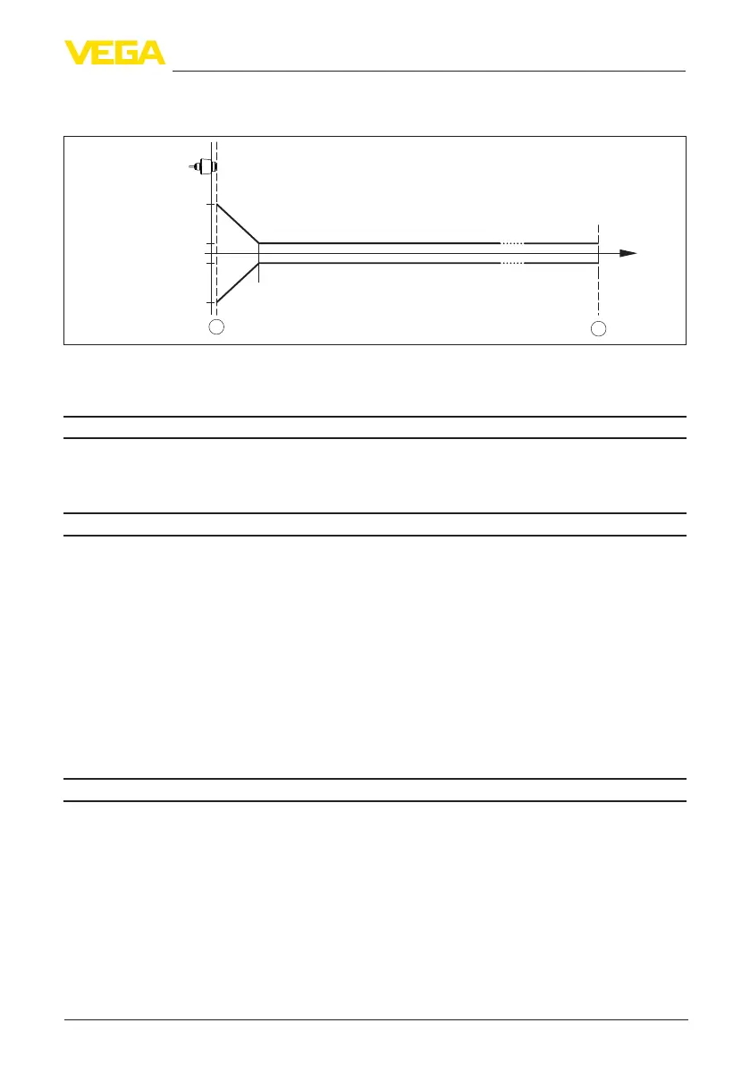
0,25 m (0.8202 ft)
10 mm (0.3937 in)
- 10 mm (- 0.3937 in)
2 mm (0.0787 in)
- 2 mm (- 0.0787 in)
0
1
2
Fig. 27: Deviation under reference conditions
9)
1 Antennaedge,referenceplane
2 Recommended measuring range
Variablesinuencingmeasurementaccuracy
Temperature drift - Digital output < 3 mm/10 K, max. 5 mm
Additional deviation through electromag-
netic interference acc. to EN 61326
< 50 mm
Characteristics and performance data
Measuring frequency
W-band (80 GHz technology)
Measuring cycle time ≤250ms
Step response time
10)
≤3s
Beam angle
11)
8°
Emitted HF power (depending on the parameter setting)
12)
Ʋ Average spectral transmission power
density
-3 dBm/MHz EIRP
Ʋ Max. spectral transmission power
density
+34 dBm/50 MHz EIRP
Ʋ Max. power density at a distance of
1 m
< 3 µW/cm²
Ambient conditions
Ambient temperature
-40 … +80 °C (-40 … +176 °F)
Storage and transport temperature -40 … +80 °C (-40 … +176 °F)
9)
Incaseofdeviationsfromreferenceconditions,theosetduetoinstallationcanbeupto+/-4mm.Thisoset
can be compensated by the adjustment.
10)
Timespanafterasuddendistancechangefrom1mto5muntiltheoutputsignalreaches90%ofthenal
valueforthersttime(IEC61298-2).ValidwithoperatingvoltageU
B
≥24VDC.
11)
Outsidethespeciedbeamangle,theenergyleveloftheradarsignalis50%(-3dB)less.
12)
EIRP: Equivalent Isotropic Radiated Power