31
Rev. 01.01
COMMISSIONING
5. COMMISSIONING
16 - Freecooling
17 - PID Parameters
18 - HW Test
20 - Modbus RTU
21 - Network
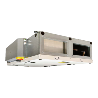
MENU 18 - HW TEST
The HW TEST menu is used to test all the con-
nected components and accessories. These pa-
rameters are not stored and the HRV will return to
normal operation upon exiting this screen
Warning: This mode allows explicit control
of the components in the HRV. There are no
protections in place to stop a user from op-
erating the unit in a potentially hazardous
manner.
The heater(s) should not be manually oper-
ated with the dampers closed nor without
adequateairowthroughtheHRV.
17 - PID Parameters
18 - HW Test
20 - Modbus RTU
21 - Network
23 - User Lock
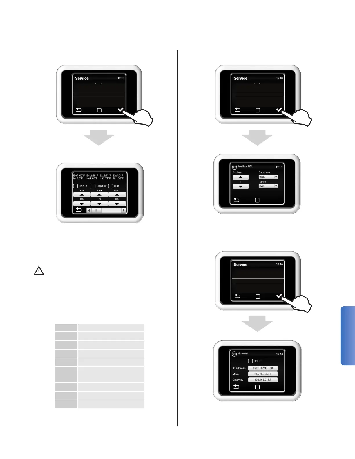
MENU 20 - MODBUS RTU
The MODBUS menu is used to set the Modbus
communication.
MENU 21 - NETWORK PARAMETERS
18 - HW Test
20 - Modbus RTU
21 - Network
23 - User Lock
49 - Other Settings
The NETWORK is used to set the unit's IPv4 con-
guration for ModBus TCP.
F in Supply Fan
F out Exhaust Fan
Pre 1 Preheater 1 Power
By/Ro Core Bypass
Ext 1 Outside Air
Ext 2
Supply Air (Post Heat
Exchanger)
Ext 3 SA (In-Duct)
Int 1 Extract Air
Int 2 Exhaust Air