Ventis™ MX4 Product Manual
27 © 2014 Industrial Scientific Corporation
Prepare the gas cylinder for use
According to the supply chart above, attach the correct regulator to the gas cylinder and turn clockwise to tighten.
Next, choose instruction A., B., or C. based on the monitor/regulator combination in use.
A. Aspirated with demand flow regulator
Attach either end of the tubing to the cylinder’s nipple.
DO NOT ATTACH THE OTHER END OF THE TUBING TO THE MONITOR BEFORE REACHING THE
“APPLY GAS SCREEN”. Completing the connection of the tubing will cause gas to flow. If gas is
applied before reaching the appropriate screen, the monitor will go into alarm and a failure will be
logged.
B. Aspirated with positive flow regulator
The calibration tubing with the t-fitting (not included) has two different sized openings, a narrow opening
at one end and a wider opening at the other end.
Attach the wider opening to the nipple on the cylinder’s regulator.
Attach the smaller opening to the pump inlet.
DO NOT APPLY THE GAS BEFORE REACHING THE “APPLY GAS SCREEN”. If gas is applied before
that point, the monitor will go into alarm and a failure will be logged.
C. Diffusion with positive flow regulator
Attach either end of the tubing to the cylinder’s nipple.
Attach the other end of the tubing to the calibration cup’s nipple.
DO NOT ATTACH THE CALIBRATION CUP TO THE MONITOR OR APPLY THE GAS BEFORE
REACHING THE “APPLY GAS SCREEN”. If gas is applied before that point, the monitor will go into
alarm and a failure will be logged.
Zero and Quick Calibration Process
Display and Options Instructions
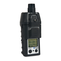
Gas Monitoring Screen
Numeric mode display (left)
Text mode display (right)
Displays the gas concentration readings (or gas names
in text mode) for all installed sensors. If a sensor is NOT
installed, its position on the LCD is blank.
Press ON/OFF/MODE to advance to the Days since
Calibration Screen.
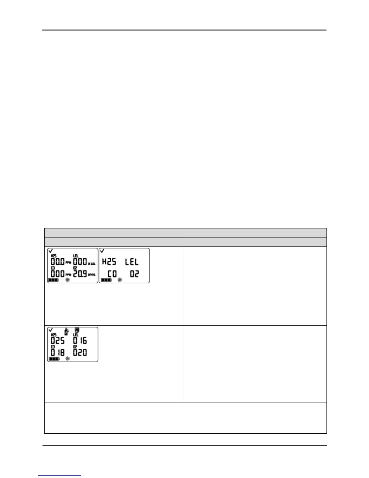
Days Since Calibration Screen
Displays the number of days since the last successful
calibration for each installed sensor. Each value can be
different.
Press ON/OFF/MODE to advance to one of three
screens.
If zero in-field is enabled, the user advances to the
Zero Initiate Screen.
If zero in-field is disabled and bump test in-field is
enabled, the user advances to the Bump Test Initiate
Screen.
If zero in-field and bump test in-field are both
disabled, the user advances to the Peak Readings
Screen.
NOTE: When zero, calibration, and bump test are ALL in-field enabled, and the user has entered zero from the gas
monitoring mode, the monitor expects to be calibrated following a successful zero.
If the desired task, after zero, is bump testing (or clearing the peaks) and NOT calibration, follow the instructions at
the Calibration Apply Gas Screen to terminate calibration.