OPERATIONAL CONTROLS
Operation - 27
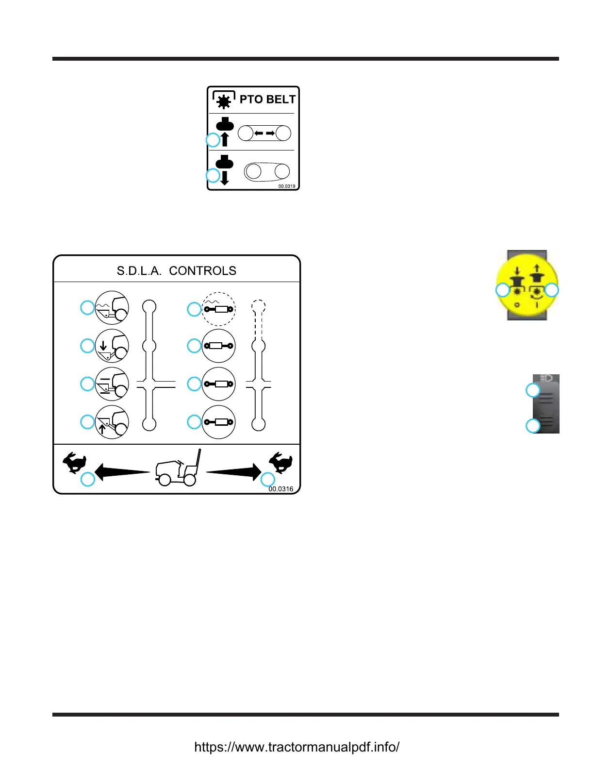
PTO Belt Tensioner Rod (L)
The PTO belt tensioner rod
1
2
applies or releases belt tension
to the attachment drive belt.
After placing the attachment
drive belt onto the PTO drive
pulley, push the PTO belt ten-
sioner rod in (1) until it locks in
position with tension applied to
the attachment drive belt.
Pulling the PTO belt tensioner rod out (2) releases
the belt tension, allowing the operator to remove or
install the attachment drive belt.
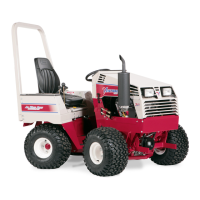
SDLA Control Lever (M & N)
1
2
3
4
5
6
7
8
9
10
1. Forward Direction
2. Reverse Direction
3. Lift
4. Hold
5. Lower
6. Float
7. Direction #1
8. Hold
9. Direction #2
10. Float (if equipped)
The SDLA (Speed, Direction, Lift, & Auxiliary) is the
primary control for the power unit and consists of two
levers. The primary SDLA control lever (M) controls the
speed, the direction of travel, and the lift of the hitch
arms. The secondary SDLA control lever (N) controls
the auxiliary hydraulic circuit.
S - Speed: the amount of forward or backward move-
ment of the primary SDLA lever controls the
ground speed of the power unit.
D - Direction: the forward or backward movement of
the primary SDLA lever controls the direction of
the power unit.
L - Lift: the lift function of the primary SDLA lever has
four positions: Up, Hold, Down, and Float Lock.
Hold is the default position and holds the hitch
arms from moving up or down. Pulling the lever
to the left raises the hitch arms. Pushing the lever
to the right lowers the hitch arms. Float position is
attained by pushing the lever to the right until the
oat detent engages and locks the lever in place.
A - Auxiliary: the left or right movement of the second-
ary SDLA lever controls the functions of the attach-
ments that require the auxiliary hydraulic circuit.
An optional oat kit (part # 23.0210) is available for
the auxiliary hydraulic circuit.
Pull the PTO switch up to the On
1 2
position (2) to engage the electric
clutch and send power to the front
attachment.
Push the PTO switch down to the O
position (1) to disengage the clutch and
stop the attachment. NOTE: the PTO
will shut o automatically if the operator leaves the
seat. To restart the PTO, cycle the PTO switch to the
O position, then back to the On position.
Headlight Switch (P)
Press the top (1) of the headlight switch to
1
2
turn on the headlights and taillights. Press the
bottom (2) of the switch to turn the lights o.
USB Receptacle (Q)
The USB receptacle has two USB charging ports with a
sealed cover.
Seat Slide Lever (R)
Lift seat slide lever up to release the seat lock. Move
the seat forward or backward to the desired position
and release the seat slide lever to lock the seat in place.
https://www.tractormanualpdf.info/