OPERATIONAL CONTROLS
Operation - 29
Work Light Switch (AA)
Press the top (1) of the work light switch
1
2
to turn on the work lights. Press the bottom
(2) of the switch to turn the work lights o.
Strobe Light Switch (BB)
Press the top (1) of the strobe light switch
1
2
to turn on the strobe light. Press the bottom
(2) of the switch to turn the strobe light o.
Directional Signal Switch (CC)
Press the left side (1) of the directional
1
2
signal switch to turn on the left turn signal.
Press the right side (2) of the directional
signal switch to turn on the right turn
signal. Return the switch to the middle
position to turn o the signals. The left and
right turn signals will override the hazard ashers.
Pressing the top (1) of the hazard asher
2
1
switch ashes both of the directional turn
signal lights. Press the bottom (2) of the switch
to turn the hazard asher lights o. Use of the
directional turn signals will override the hazard
ashers until the turn signal is turned o.
Horn Switch (EE)
Press the horn switch to sound the signal horn. The
horn will sound until the horn switch is released.
12 Volt Front Switches and 4-Pin Socket
(FF, GG, and HH)
ATTENTION
The 4-pin socket is designed for use with Ventrac
original equipment only.
This connector is rated for 20 amp maximum
current draw. The engine alternator and/or battery
capacity determine allowable continuous draw.
1
2
3
4
The front 4-pin socket
provides electrical
power to attachments
that are equipped
with electrical controls
(e.g. broom rotation
actuator, snow blower
discharge chute angle).
The switches turn o
and on the electrical
power to the front 4-pin socket.
Press the top (1) of the rocker switch to turn on the
electrical power to the 4-pin socket. Press the bottom
(2) of the rocker switch to turn o the electrical power.
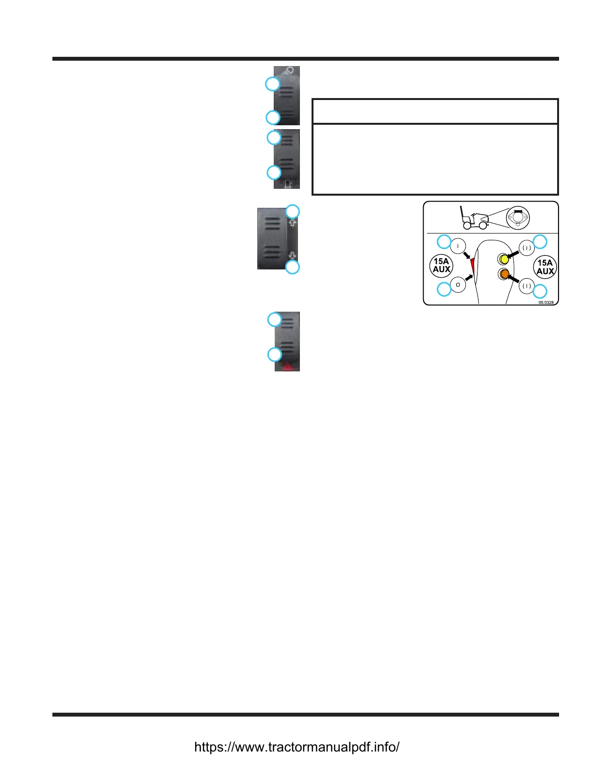
Press and hold either the top (3) or bottom (4) mo-
mentary switch to turn on the electrical power to the
4-pin socket. Release the switch to turn o the electri-
cal power.
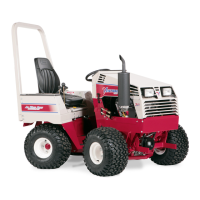
Dual Front Hydraulic Auxiliary Switch (II)
The optional switch handle is part of the dual front
hydraulic auxiliary kit and is used to select which set
of quick couplers is controlled by the secondary SDLA
lever. The secondary SDLA lever operates the quick
couplers with the red and yellow indicators until the
button on the handle is pressed. Press and hold the
button to switch the secondary SDLA lever to operate
the quick couplers with the white and black indicators.
Release the button to return to normal operation.
Dual Front Hydraulic Auxiliary Valve (JJ)
The dual front hydraulic auxiliary valve is used with
attachments that are equipped with four hydraulic
hoses. The valve uses a switch on the secondary SDLA
lever to operate the desired set of quick couplers.
https://www.tractormanualpdf.info/