SERVICE
Service - 55
TCS (Tractor Control System) Explanation
The tractor control system controls the electronic
safety related functions of this power unit. Both solid
state and mechanical components are used to ensure
the safe, reliable operation of this machine.
This TCS monitors the electronic circuits necessary for
the engine, the starter, and the PTO to function. These
input circuits include the PTO switch, the neutral
switch, the parking brake switch, the ignition switch,
and the seat switch. The TCS allows the engine, the
starter, or the PTO to operate only when specic input
criteria are satised. The engine, the starter, and the
PTO are controlled by outputs from the TCS.
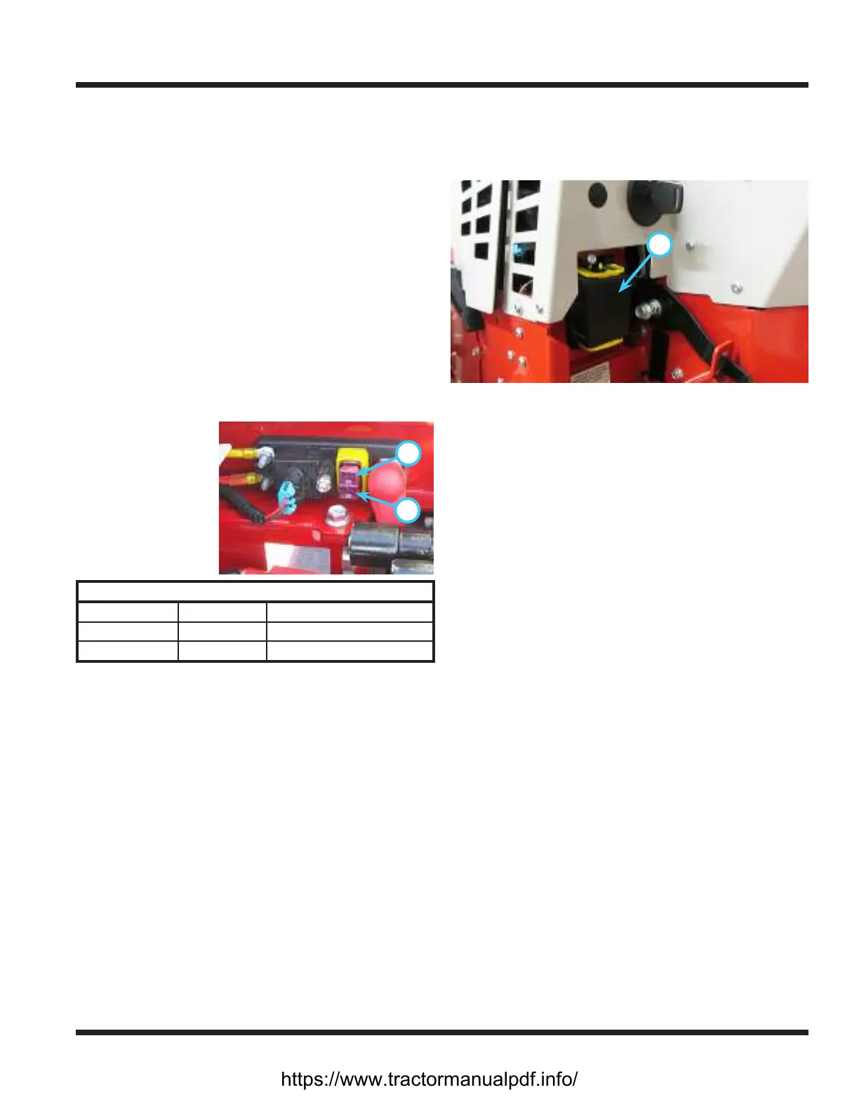
Replacing Fuses (Power Relay Module)
1. Turn the battery disconnect switch to the O
position.
2. Tilt the seat forward and fasten in place with the
seat prop.
A
B
3. Remove the
sealed fuse cap
from the power
relay module.
4. Identify and
remove the de-
fective fuse from
the socket.
Power Relay Module (J-Case Fuse)
Position Fuse Circuit
Top (A) 50 amp Key Switch, TCS
Bottom (B) 50 amp Rear Fuse Panel Supply
5. Insert a new fuse into the socket. Be sure the fuse
is the correct amperage or damage may occur to
the power unit.
6. Reinstall the sealed fuse cap and lower the seat
back down to the operating position.
7. Turn the battery disconnect switch to the On
position.
Replacing Fuses (Front Fuse Panel)
1. Turn the battery disconnect switch to the O
position.
2. Remove the sealed cover (A) from the fuse panel.
3.
A
Identify and remove the defective fuse from the
socket. Refer to the Quick Reference decal under
the hood for fuse locations.
4. Insert a new fuse into the socket. Be sure the fuse
is the correct amperage or damage may occur to
the power unit.
5. Reinstall the sealed cover onto the fuse panel.
6. Turn the battery disconnect switch to the On
position.
https://www.tractormanualpdf.info/