ELECTRICAL INSTALLATION
10 B001686
ELECTRICAL INSTALLATION
WARNING
• Refer to the safety rules described in the electrical connections section of the safety information
chapter of this document!
Depending on the configuration, insert the cable into the 8-pin and 14-pin contact enclosure according to
the following pin assignment.
The contacts must audibly lock into place.
Now insert the plug into the gauge.
Note the inverse polarity protection nose in the process.
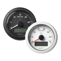
PINOUT 8-PIN CONNECTOR
Pin No.
Wire color Description
1 Red KL. 30 – Battery Power 12 / 24 V
2 Black KL. 31 – Ground
3 Black / Blue Sensor ground
4 Brown KL. 15 – Ignition plus
5 Green Sensor signal
6 Blue / Red KL. 58 – Illumination
7 Yellow / Black Programming port Tx
8 Yellow / Red Programming port Rx
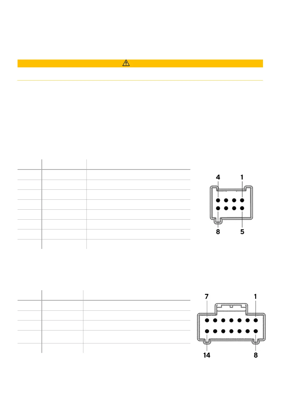
PINOUT 14-PIN CONNECTOR
These connections apply for the tachometer versions with LCD only.
Pin No.
Wire color Description
1 - 10 - N.C.
11 Black / Green Configuration key
12 Red / Green Mode key
13 Red
(Not available on the standard VL gauges)
14 - N.C.
* Open Collector – 100mA max.
 Loading...