MECHANICAL INSTALLATION
7 B001686
INSTALLATION WITH SPINLOCK
Conventional assembly. (Instrument is put into the drill hole from the front).
The panel thickness may be within a range of 2 to 18 mm.
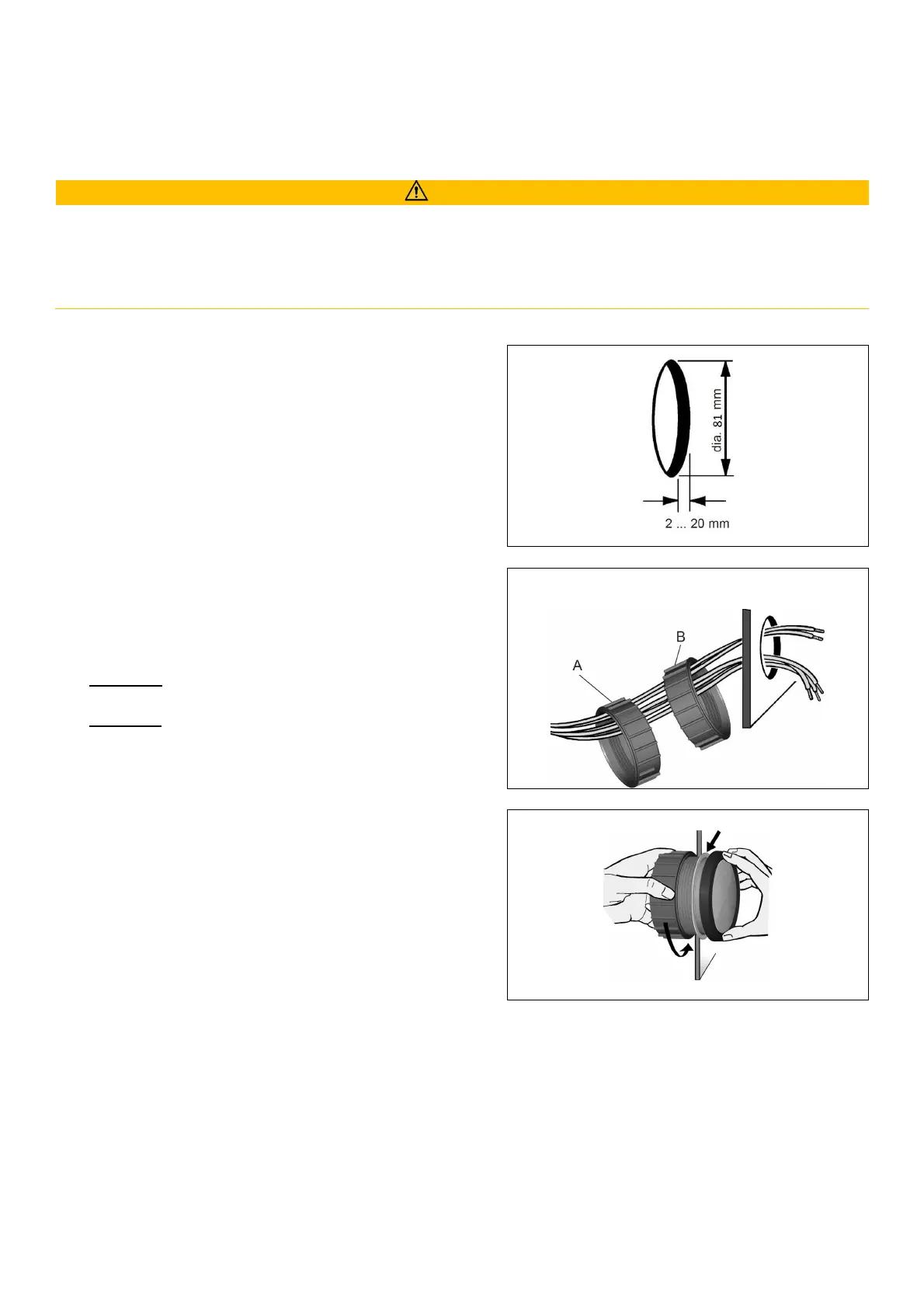
The drill hole must have a diameter of 81 to 86 mm.
WARNING
• Do not drill holes or ports in load-bearing or stabilizing stays or tie bars!
• Note the necessary clearance behind the drill hole or port at the installation location. Required
mounting depth: 65 mm.
• Drill small ports; enlarge and complete them, if necessary, using taper milling tools, saber saws, keyhole
saws or files. Deburr edges. Follow the safety instructions of the tool manufacturer.
1. Create a circular hole in the panel considering the
device dimensions.
2. Remove the spinlock and insert the device from
the front.
3. For 85 mm instruments, the fastening nut can be
mounted at position A or B. This allows you to fix
the gauge in different panel bores.
Version A
Panel bore 80.5 – 81 mm
Version B
Panel bore 85.5 – 86 mm
4. Align the instrument and hand-tighten the
fastening nut. Ensure that the nut is not tightened
with a torque greater than 4 Nm.
5. Make sure the seal lays flat between the panel and
the front ring.
 Loading...