SETUP
Smart Card Reader
22 P400/P400 PLUS INSTALLATION GUIDE
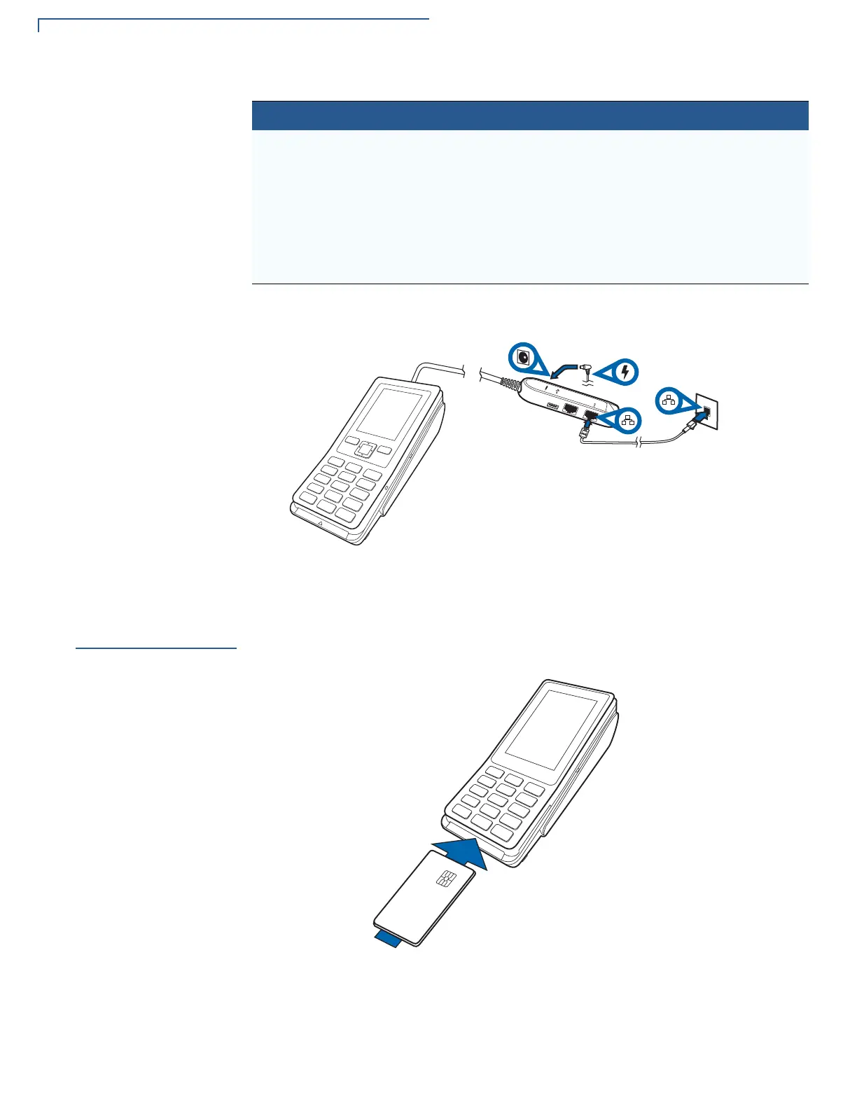
The figure below shows the connections available on the external power brick.
Figure 14 Available Connections on the External Power Brick
Smart Card
Reader
The smart card transaction procedure can vary depending on the application.
Verify the proper procedure with your application provider before performing a
smart card transaction.
Figure 15 Using the Smart Card Reader
Ethernet and Mini-
USB option
Junction box with RJ-45 socket (for
connecting PINPad to LAN
infrastructure), MOD-8 socket, Mini
USB & DC-in jack
CBL435-005-02-A
Ethernet with RS232
and USB option
Junction box with RJ-45 socket (for
connecting PINPad to LAN
infrastructure), MOD-8 socket, Mini
USB, type A USB & DC-in jack
CBL435-044-01-A
Cable Configuration Part Number
 Loading...