SERVICE AND SUPPORT
Accessories and Documentation
P400/P400 P
LUS INSTALLATION GUIDE 35
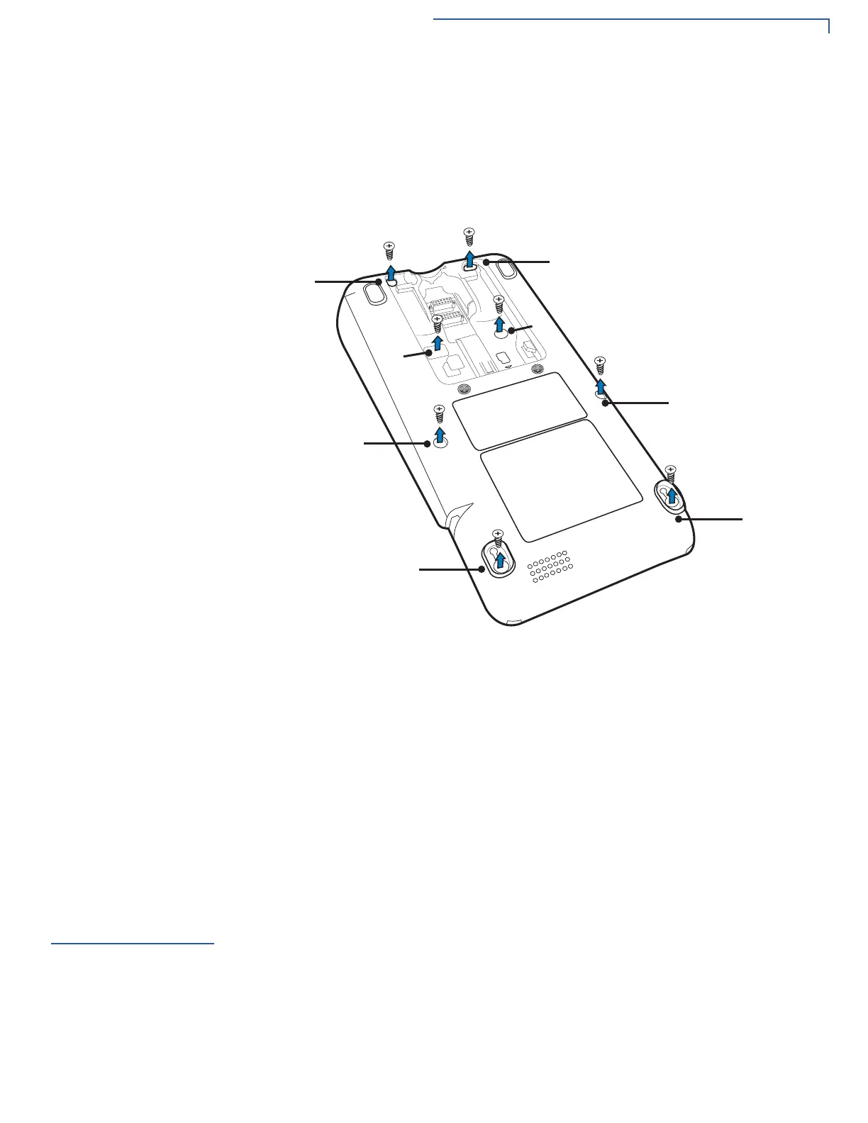
4 Using the Phillips head screw driver, remove each of the eight screws. Four of
the screws (screw numbers 3, 4, 5, and 6) are covered by the rear cable
cover. You must remove the cable cover to access these screws.
Screw #4 is covered by a tamper-evident security label. Push the screw driver
through this label to access the screw.
Figure 20 P400 Bottom
5 Once all the identified screws have been removed, carefully separate the top
housing plastics from the bottom 1mm, then pinch the top and bottom housing
back together ensuring proper fit.
6 Reinsert all of the screws previously removed. Tighten each screw completely.
7 Insert the power cable and power up the device.
8 Turn the device face up showing the display and keypad. Verify that the unit is
in an “Active Tamper.” You should see the *TAMPER* message displayed on
the screen.
Accessories and
Documentation
Verifone produces accessories and documentation for the P400. When ordering,
please refer to the part number in the left column.
• Verifone Online Store at www.store.verifone.com
• USA – Verifone Customer Development Center, 1-800-Verifone (837-4366)
Monday - Friday, 7 A.M. - 5
P.M., MST
• International – Contact your Verifone representative
 Loading...