DEVICE SETUP
Using the e355 Frame
24 E355 INSTALLATION GUIDE
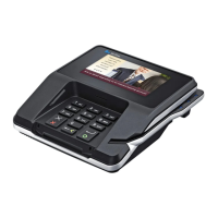
2 Extend the front part to match the screw holes then insert and tighten the
screw to secure e355 terminal. The figure below shows which screw to use.
Figure 20 Securing the e355 Terminal
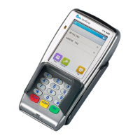
To remove the e355
from the Frame
1 Remove the screw at the front of the frame.
Figure 21 Removing the Screw
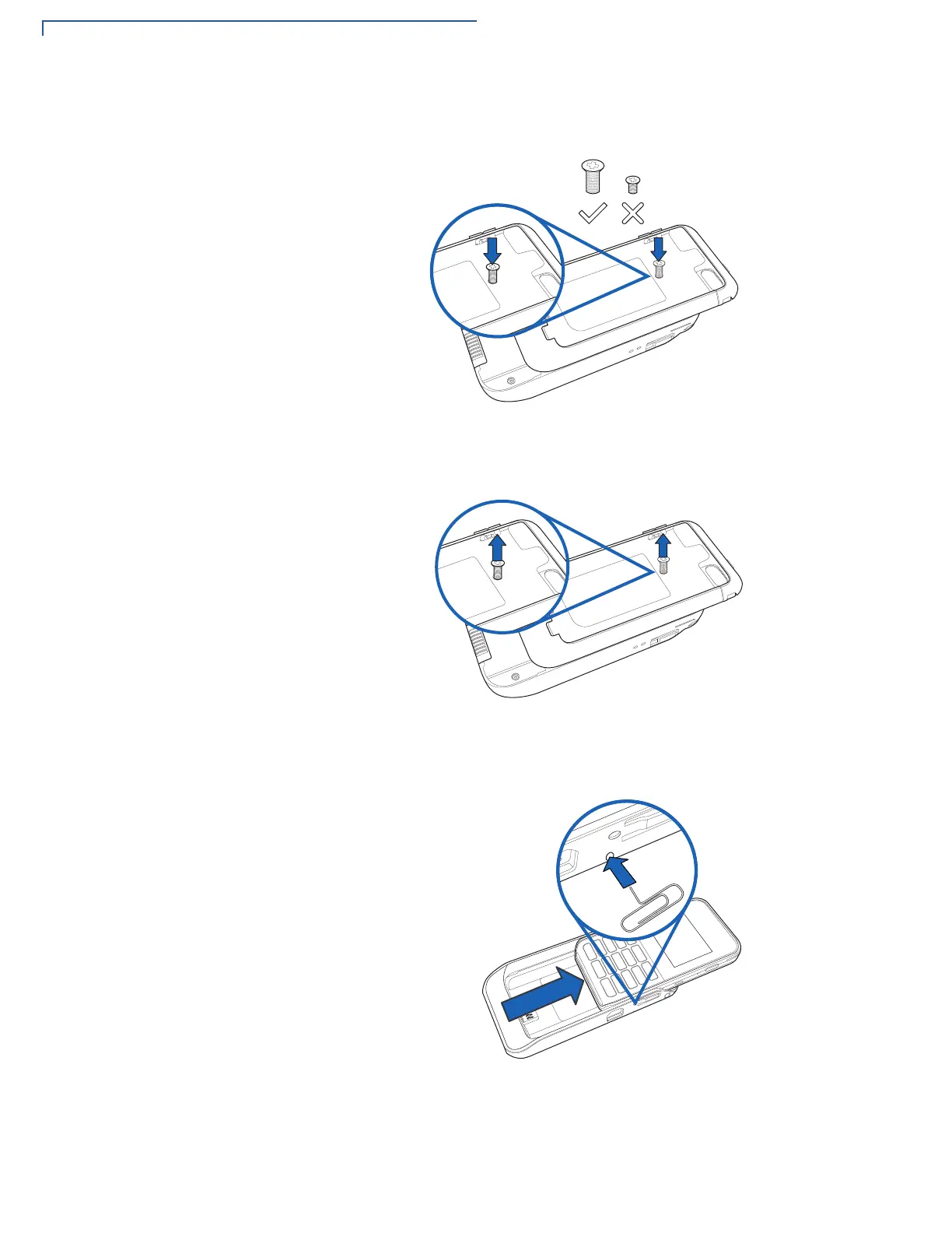
2 Insert a paper clip or a similar tool in the hole located on the side of the frame
just below the Power LED indicator and then slide the e355 terminal upwards.
Figure 22 Inserting a Paper Clip to Remove the e355

 Loading...