Installation and Operation Guide
www.trutankless.com Bollente trutankless® VERO Series Water Heaters
9
PRODUCT MODEL SETTINGS
IMPORTANT: IDEAL PERFORMANCE OF THE TRUTANKLESS SYSTEM
DEPENDS ON COMPLIANCE WITH THIS SECTION.
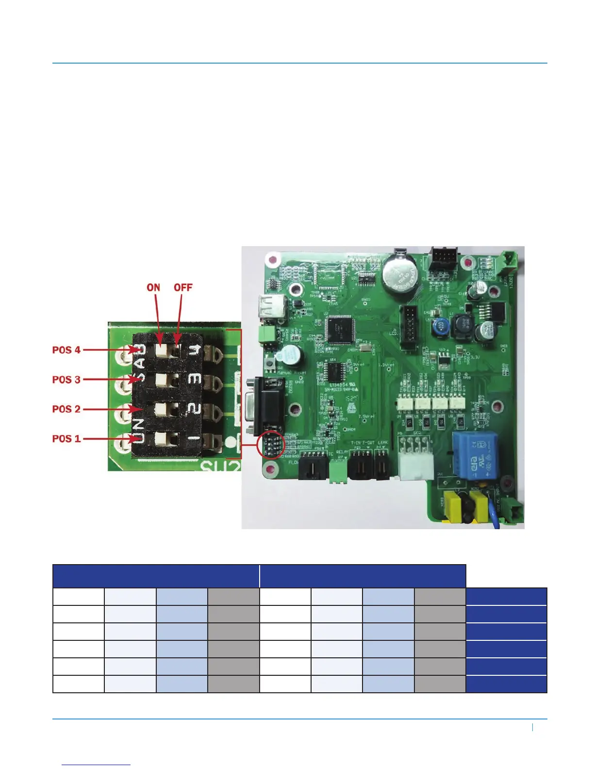
e DIP switch positions determine the performance parameters of the unit model. To ensure proper installation and system
operation, the unit MUST be congured using the DIP switches settings specied in Table 2 below and pictured in Table 3 on
the following page. Following these instructions and properly setting the DIP switches at installation is extremely critical to the
proper functioning of the system and willensure ideal temperature rise and flow rate maximums.
Figure 1 — Dip Switch Pin Locations
Table 2 — DIP Switch Settings Per Current Limit
RESIDENTIAL MODELS COMMERCIAL MODELS
POS 1 POS 2 POS 3 POS 4 POS 1 POS 2 POS 3 POS 4 Current Limit
OFF ON ON ON OFF ON ON ON 60A
ON OFF ON ON ON OFF ON ON 80A
OFF OFF ON ON OFF OFF ON ON 100A
ON ON OFF ON ON ON OFF ON 120A
ON ON ON ON ON ON ON ON 160A