Installation and Operation Guide
www.trutankless.com Bollente trutankless® VERO Series Water Heaters
15
NOTE: Bollente recommends covering the unit with plastic or other impermeable sheeting until all water connections have
been installed and tested, to protect the internal parts from potential leaks. Leave the tubing manifold connections uncovered
for access.
Next, the unit must be connected to the local potable water supply.
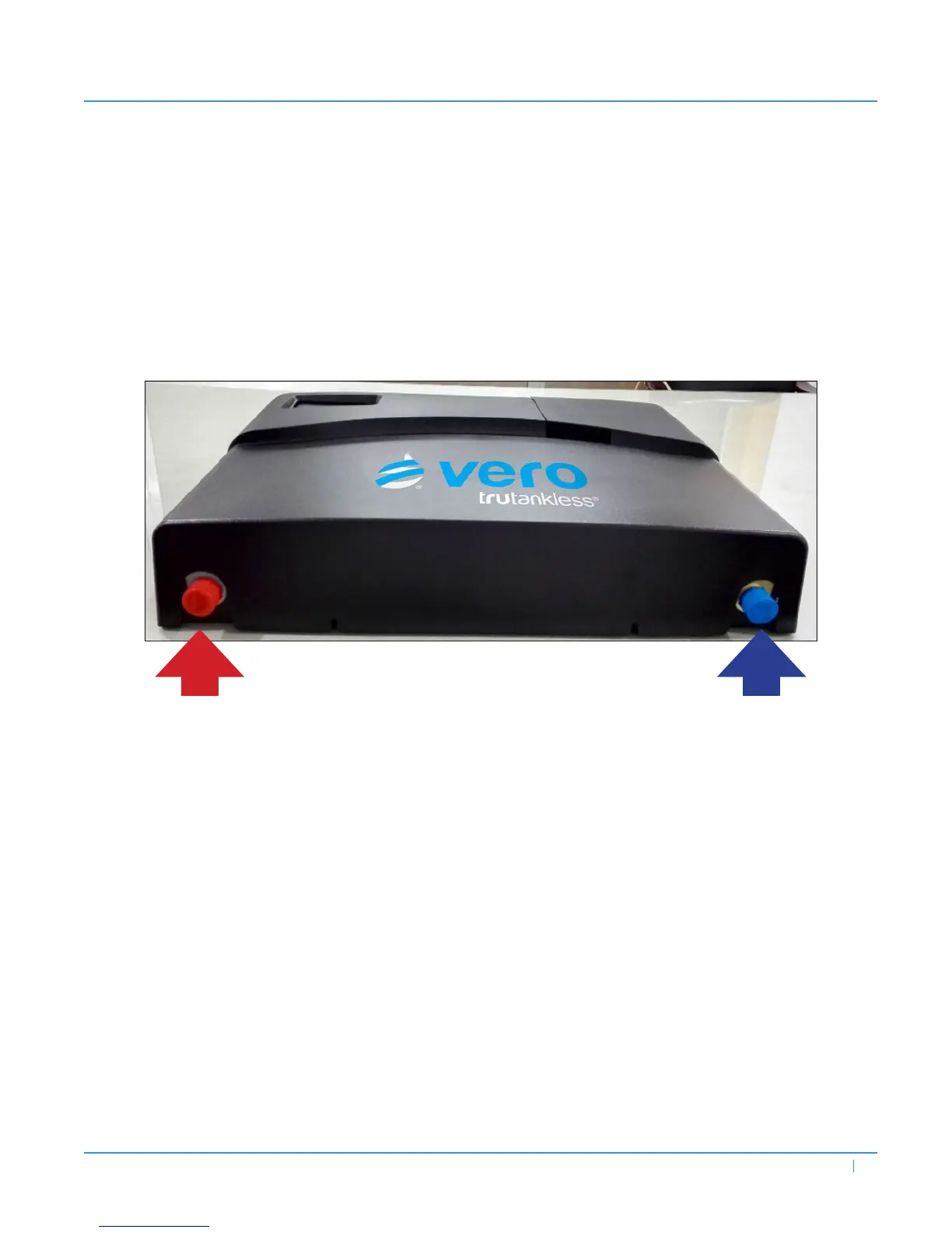
e VERO BR/BC has two plumbing connections:
• ¾˝ MNPT male (blue) cold water supply inlet (rightmost when facing the unit)
• ¾˝ MNPT male (red) hot water outlet
Figure 5 — Plumbing Connections
C W I C (B A)
First, connect the inowing Cold Water Supply to the INLET connection, indicated by the Blue “Inlet Water” tag. is is
accomplished by connecting the recommended ¾˝ x 12˝ stainless steel braided ex hose from the potable cold water supply to
the unit’s ¾˝ NPT inlet. Using a wrench, attach the stainless ex lines to the inlet connection.
NOTE: Take care to NOT over-torque these connections (both cold and hot.) Doing so induces stress on the heating manifold
assembly. Manifolds damaged by over-tightening these connections are NOT covered by warranty.
NOTE: e VERO BR/BC unit is shipped with an in-line screen lter which should be inserted in the cold (inlet) connection.
e use of this lter is optional, but it is highly recommended, especially in new constructions where debris may be present
in the line. e gasket is placed over the domed side of the screen, then the domed side is inserted into the cold (inlet) pipe so
that the gasket is between the pipe and lter ring. Ensure that the assembly is well-seated with no gaps between the inlet pipe,
gasket, and lter ring before attaching the ex line to the connection.
H W O C (R A)
Next, connect the outowing Hot Water Supply main to the Outlet connection, indicated by the Red “Outlet Water” tag. is
is accomplished in a manner identical to connecting the inlet supply.
Turn on the water supply to the system. Open a hot water tap in the house to allow water to ow.
NOTE: Outowing water will be cold at this point of installation. Water will not ow hot until electrical supply is connected.
Verify that the inlet and outlet connections are leak-free, both with water owing and with the water ow stopped. Maintain
water pressure and check for leaks for a minimum of ten (10) minutes. If a slight leak is noted at either of the stainless steel
exible line connection points, carefully tighten further with both wrenches as noted above.