INSTALLATION
2-3
VersaPulse Select Service Manual
0621-499-01 12/95
®
®
The shipper is responsible for any damage to the system in shipment. If the crate/carton appears to
be damaged, report the damage to the customer and shipper.
3.) Remove the console and accessories from the crate.
Refer to drawing 2-1. Remove the straps, remove the top cover, remove the side cover, remove the
protective foam, remove the accessories box, then locate and remove the two wooden ramps stored in
the base. Lower the lift plates (2) by turning the bolt at each end of each lift plate (5/8" and 3/4"
bolts). Loosen the bolts all the way, then remove the bolts and lift plate. Remove the front fence from
the base by removing the four wing nuts that secure it to the base. Install the ramps onto the base,
then roll the unit down the ramps.
4.) Move the system to its installation location.
The VersaPulse Select rolls best when pushed from the front handles. The front wheels swivel, the
rears wheels do not.
6.) Open/remove covers and do a visual inspection of the interior.
Refer to Section 5 for information on removing the covers. Open the front cover, then remove the top
and two side covers. Inspect the interior carefully for loose or broken electrical connections, loose or
broken plumbing connections, or any indication of shipping damage.
7.) Set up for site AC.
Measure the voltage of the site electrical service at the point where the VersaPulse Select will be
connected. The three connections include an earth ground and two hot mains. Measure line voltage
across the two hot mains. Mains voltage must be between 200 and 240 VAC, 50/60 Hz. Confirm that
the circuit is rated for 30 amps.
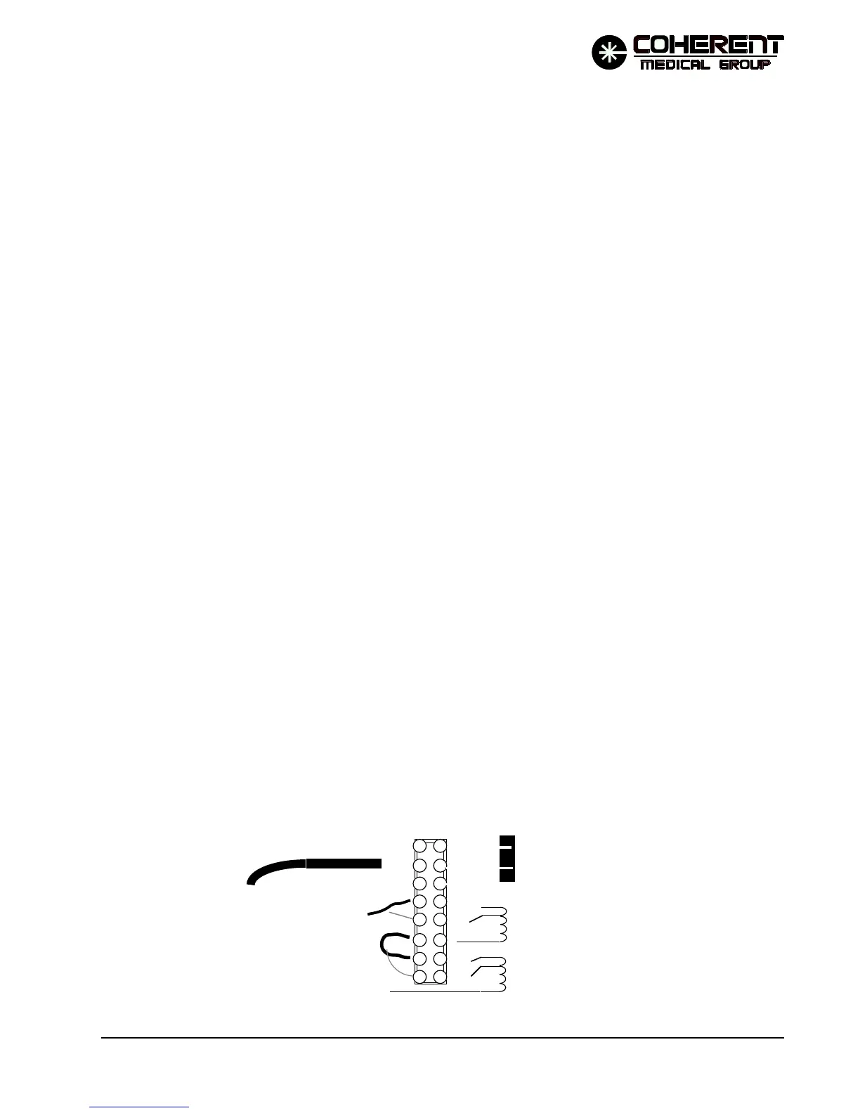
The isolation transformer has two secondaries: one operates the turn-on circuitry and the other
provides AC to the low voltage power supply, display power supply, fan and pump. These
secondary loads (not the turn-on circuitry) are rated for 220 VAC supply input. The isolation
transformer is tapped to allow a range of AC line inputs ( 200 to 240 VAC) to be stepped up or down
to result in a secondary voltage at or near 220 VAC to these secondary loads. The various taps on the
isolation transformer are wired out to terminal board TB1 on the right side on the system. The
tapping is done by changing the connections at the terminal board.
ISOLATION
XFORMER
(primary)
MAINS ( from F2)
120
100
120
100
MAINS (from F1)
POWER CORD
TB1
MAINS TO CIRCUIT BREAKER
EARTH GROUND TO
GROUNDING STUD
03/94
FIGURE 2-2 TB1 TAPPING