THEORY OF OPERATION
4-15
Versapulse Select Service Manual
0621-499-01 01/94
®
®
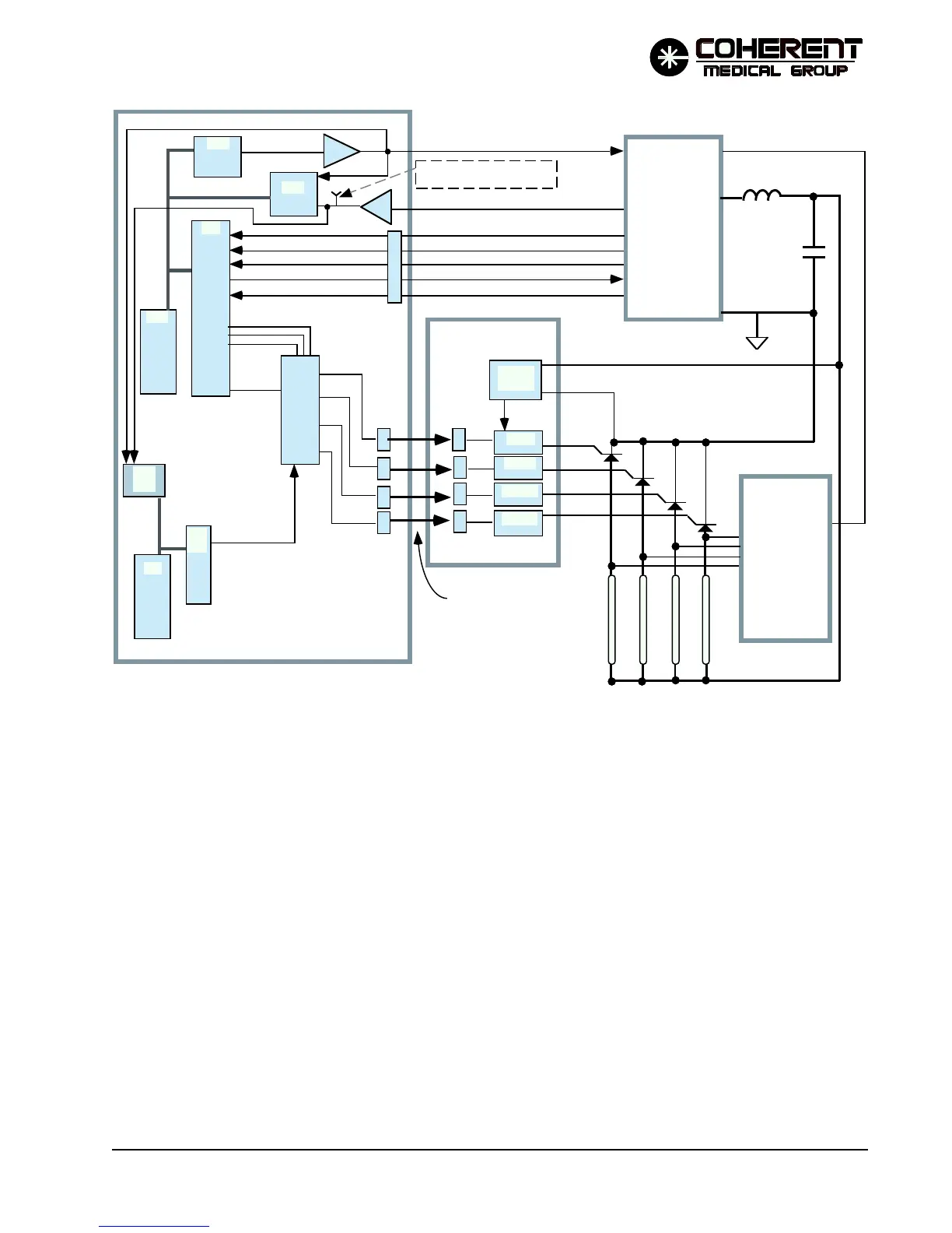
With the charge level information calculated and available on the HVDAC line, the main processor asserts its
digital I/O signal HVPSENBL (U43 pin 6). The HVPS signal is applied to U64 pin 9 and as the B input to
monostable multivibrator U65. U65 is triggered to its set state for a 50 msec period each time the B input goes
high (more than enough time to charge the capacitor). The multivibrator insures that in no case can an enable
to the HVPS last longer than 50 milliseconds. This prevents damage to the supply if the HVPSENBL signal
should hang up in the high state. The Q output of U65 is the other input to AND gate U64-8. The output of
U64 -8 (HVENTM) is anded with the /NOFIRE/ signal at AND gate U64-3. The /NOFIRE/ signal is set low
by the safety processor to disable the HVPS when it detects a problem with system operation. Otherwise /
NOFIRE/ is high, and the output of U64-3 follows the HVENTM signal. The output of U64-3 is sent through
inverter U40-6 to drive opto-isolator U100, and on to the HVPS as RS ENABLE. When this signal is asserted,
the HVPS begins charging to the level indicated by the HVDAC signal.
The HVPS provides a CAP FD BK signal to the CPU through U101, U13 and U15. The signal is 5 to 10 VDC
for a cap charge level of 700 to 1500 Volts. Both the main and safety processor ADC circuits read this voltage.
FIGURE 4.4 HVPS & PFN CONTROL CIRCUITS SIMPLIFIED DIAGRAM
12/95
P/O CPU PCB
Isolated Trigger PCB
HVPS
FLASHLAMPS
SCR'S
MAIN CHARGING
CAPACITOR
TEMP OL
CURRENT OL
NO CAP
RS ENABLE
CHARGE
OPTICAL FIBER
CONNECTIONS
FIRE SELECT
LINES
/FIREPLS/
TRG I
TRG II
TRG III
TRG IV
Mµp
ADC
U14/15/101
DIO
DAC
/NOFIRE/
SµP
DIO
CAP FD BK
HVPS DRIVE
HVDAC
SµP
ADC
SµP
C
TRG I
TRG II
TRG III
TRG IV
I II III
IV
TP11 (CAP VOLTS, 5 to 10 VDC
for 700 -1500 VOLT cap charge)
(HVDAC is 0 -5 VDC for 700 to 1500 Volts of requested cap charge for Ho only, 200 - 1500 Volts for dual wavelength)
SIMMER
P/S
U14/15/101
400 VDC Simmer Supply Voltage
OPTO
ISO
XMTR'S
RCVR'S
30 V
ZENER